Large Scale Central

1/8th scale Baldwin Westinghouse Electric Freight Motor

In the very early 1900’s, Henry Huntington started Pacific Electric Railway here in Southern California. He was the nephew of Collis Huntington, one of the Big Four of Central Pacific. The other three were Charles Crocker, Leland Stanford and Mark Hopkins. The automobile wasn’t common in those days and people needed a faster way to get around the towns of So. California. Soon P.E. became the home of the famous Red Cars and you could travel anywhere in the area for just a few pennies. It’s worth noting that all of the major freeways in So. California now occupy the same old routes of the Pacific Electric Red Cars. By 1910, Southern Pacific was shuttling local freight by steam engines. Huntington decided to corner that market by using heavy electric freight motor engines. Baldwin Locomotive and Westinghouse jointly designed one of these engines for use in the Northern California area around Oakland and San Francisco. These were 1200 volt engines using a oantograph. Central Pacific was using these for freight around the Bay Area. Huntington brought one of these engines down to So. California to try them out as heavy freight hauling engines. The photo below shows that first locomotive. P.E. converted the engine to 660 volts DC and used the familiar P.E. pneumatic trolley pole. It was renumbered from Central Pacific #200 to Pacific Electric #1611. #200 weighed in at a heavy 50 tons, pretty heavy for 1913.

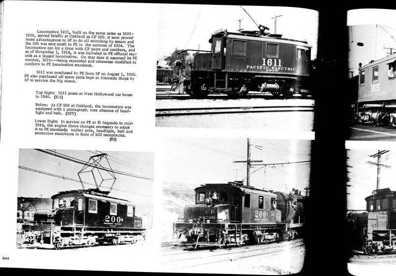
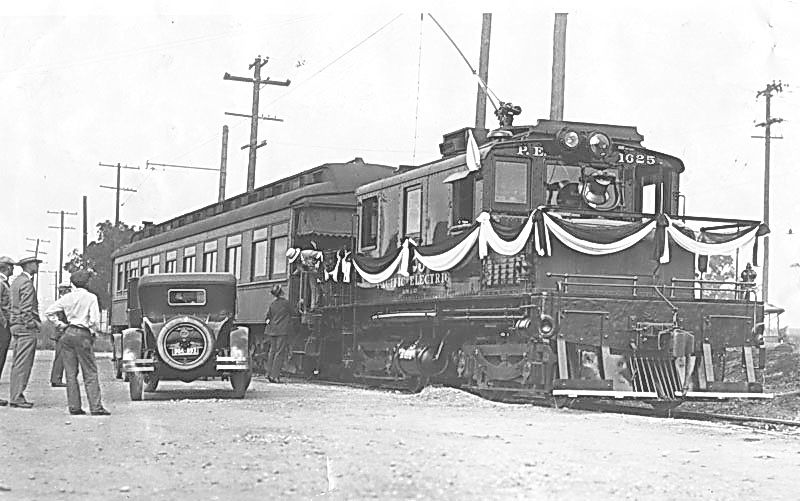
They even used one of the Baldwin electrics to pull Henry Huntington’s funeral train in May 1927. What surprised me from this photo of the funeral train was that the car used to carry Huntington’s casket was NOT the famous Funeral Car named Descanso. The crew must have spent weeks polishing the cab of this engine!

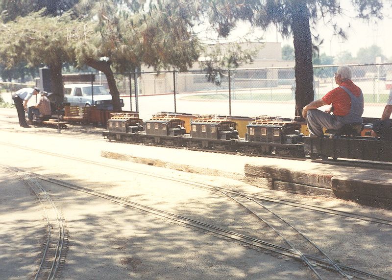
Fast-forward to the late 1970’s when West Valley Live Steamers decided to resurrect #200 and they designed and built 22 models in 1-1/2 inch scale on 7-1/2 inch gauge track. The photo below shows the first 22 electrics running on Seymour Johnson’s Montecito estate track.

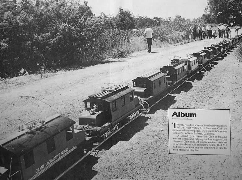
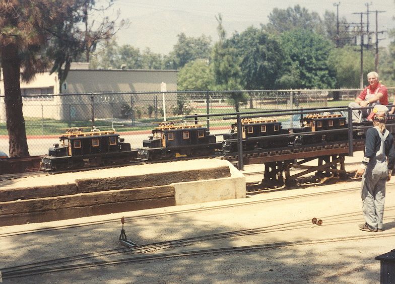
This photo was taken about 1980. A year or so after this photo, Los Angeles Live Steamers started a 24 engine project with numerous members involved and headed by Dr. Lew Soibelman. Photo below shows Dr. Soibelman running his four completed Baldwin electrics MU’ed about 1985. Notice he had BOTH a pantograph and a trolley pole on each engine. I guess he wanted to cover all his bases :).

I became involved with the 24 engine project in 1984. We completed our engine in 1986. We experimented with a couple of electrical systems before finally settling on the one in this completed engine below. Taken in 1992 at Orange County Model Engineers in Costa Mesa, CA.

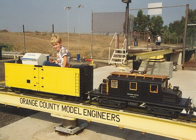
The “little guy” that’s doing the engineering here is now 33 years old!

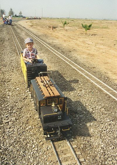
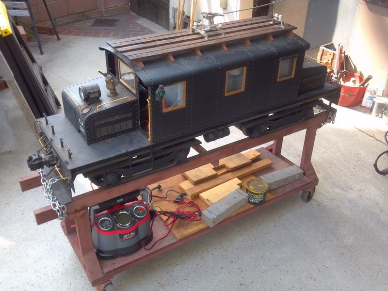
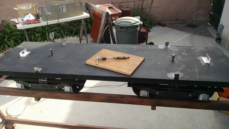
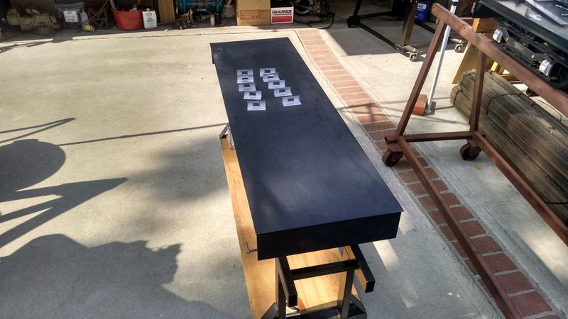
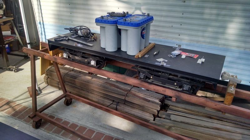
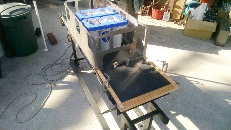
But I digress…moving on to 2013, my daughter with our one granddaughter at that time, asked if I could get my electric locomotive out and get it running again, so she could take her daughter to Los Angeles Live Steamers. Our three kids all grew up at LALS running trains, doing “night runs” and generally having a great time. She wanted her own daughter to enjoy the same great fun. So Grandpa got the old engine out of “mothballs”/storage and took a look to see what it would take to get it going again. After almost thirty years since this engine was first completed, there have been major changes in technology for the electronics to control these. The original electronic were all heavy, clunky mechanical relays and diodes. All of these were giant energy hogs. Photo below shows the old engine just out of storage in May 2013.

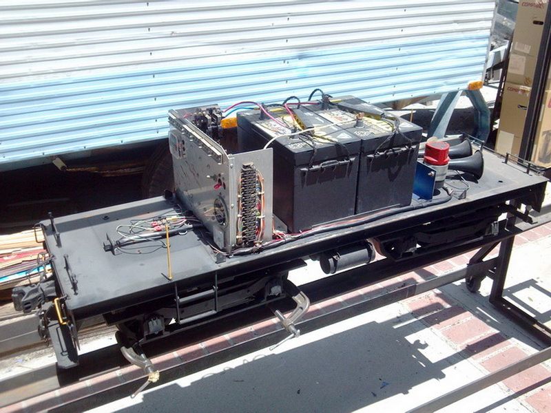
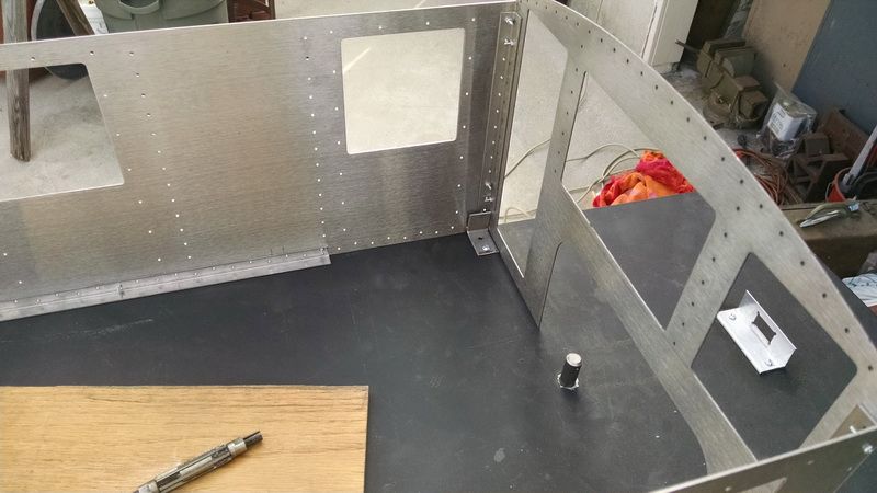
We found a man at the club who was beginning to retrofit these old Baldwin electrics with the latest and greatest technology in controllers. I gave him “free-rein” to completely redo the electronics in the old engine. By early 2014, the old Baldwin electric was running better than ever.

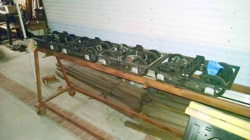
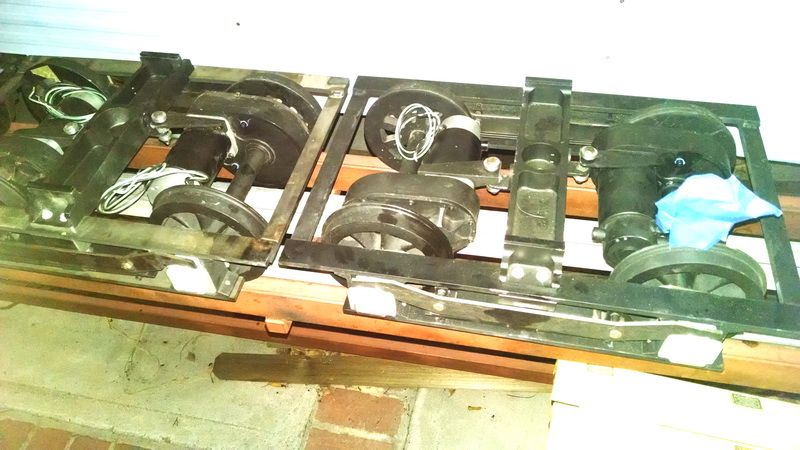
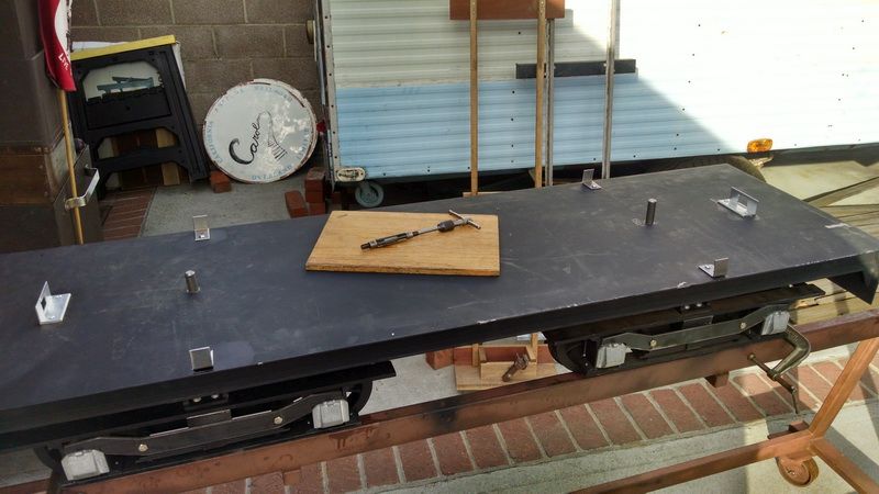
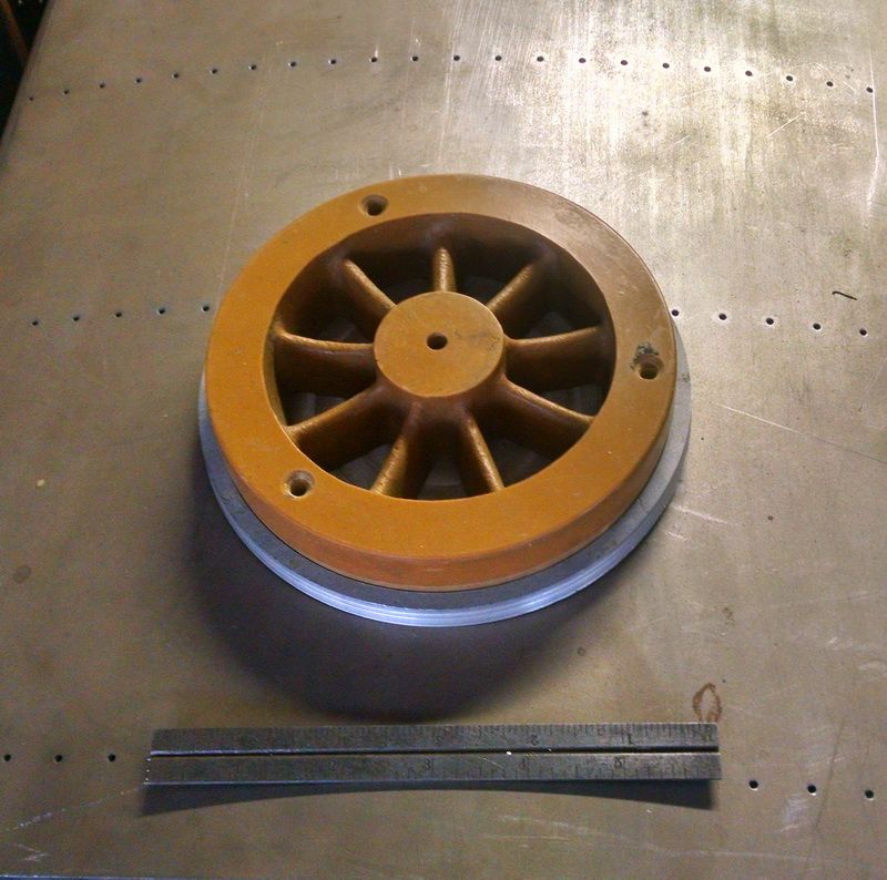
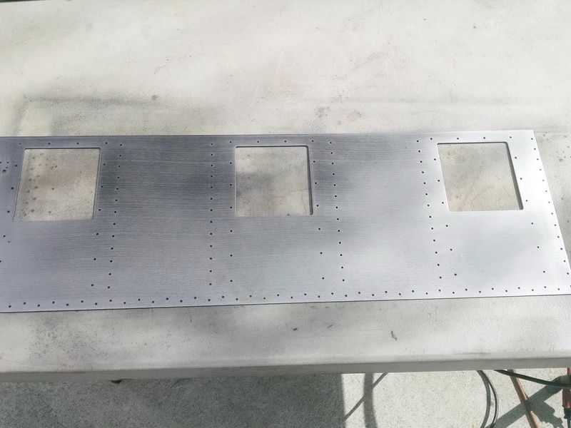
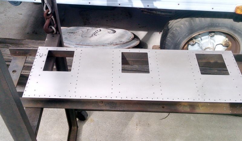
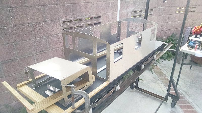
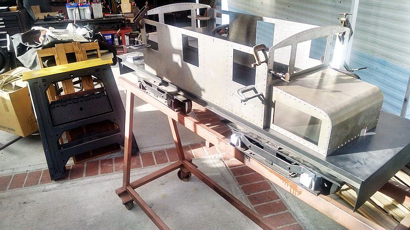
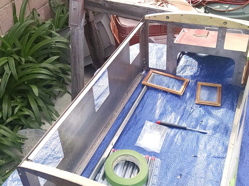
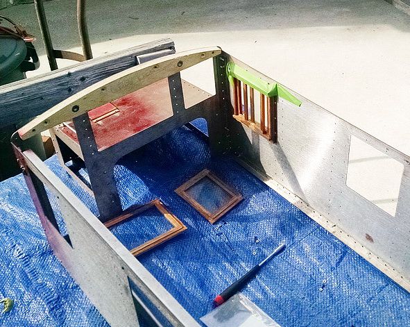
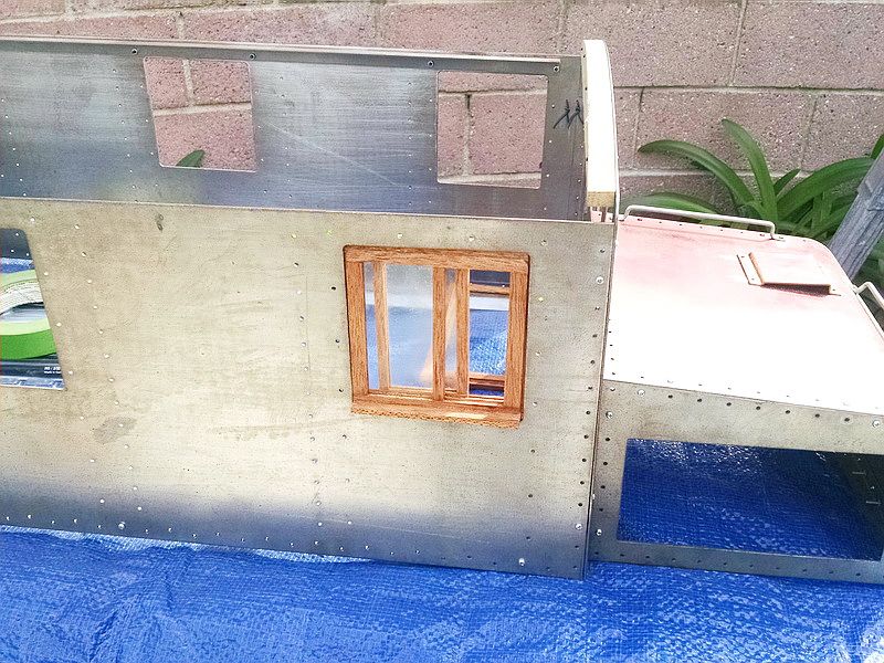
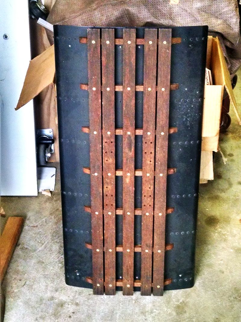
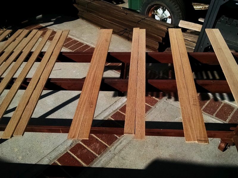
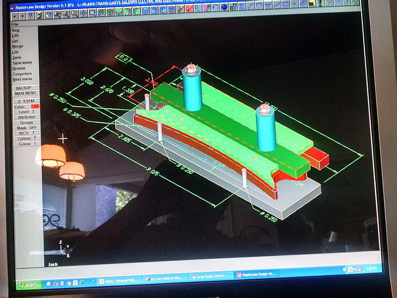
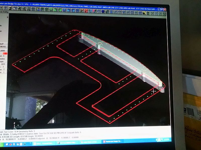
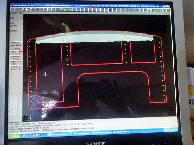
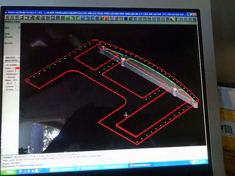
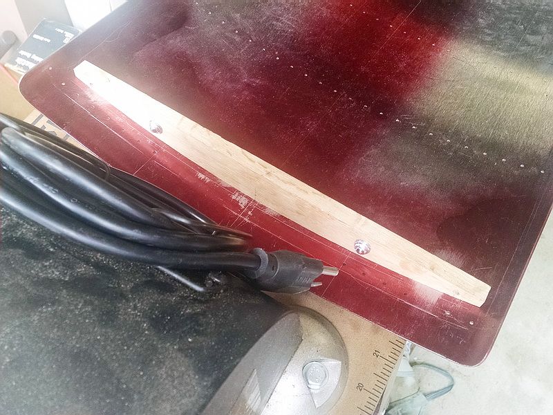
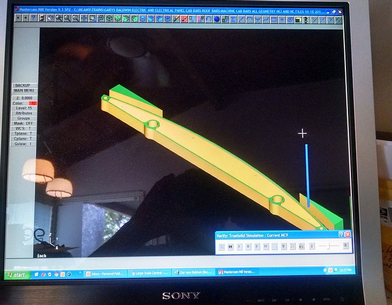
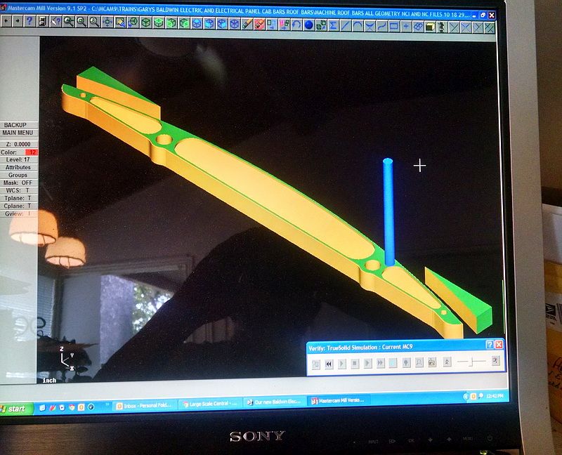
In mid 2014, I was in contact with my old college professor again. He was also a member of LALS. About 1995, he and I had started to build seven more of these locomotives as a learning project for using MasterCam software (for programing) and using Haas vertical CNC milling machines to make parts. Everything on these locomotives was designed using MasterCam and making all the parts we needed: trucks, aluminum gear boxes, truck bolsters, journals and even cast iron spoked wheels. We even had the cabs done by computer: all rivets holes, windows cut out of 16ga. steel and even had the Baldwin roofs punched and rolled by computer.

Tomorrow, I’ll add more photos and “ramblings” of this build of our new Baldwin/Westinghouse electric freight motor.

Cool!

Continuing on…

We made our own trucks (we had to, they are not commercially available). Made of steel bar stock and arc welded. The journal boxes are aluminum hog-outs made from 6061 T6 aircraft aluminum. I drew them up on MasterCam using parabolic surfaces, programmed the tool paths and milled them in a Haas 3-axis vertical mill. The gear box bodies and covers were also drawn in MasterCam as well and programmed and machined in the Haas mill. The gears are completely enclosed in a sealed environment. The truck bolsters were drawn, programmed and machined in the Haas mill.

Two pairs of powered trucks. We made seven pairs all totaled.

Close up of a single pair of trucks. The motors are 24 volt, 1/8th HP bicycle assist motors. Two motors per truck. Ball bearings in the journal boxes.

The frames/chassis are welded 1/2 inch by 1-1/2 inch steel channel with a .090 thick solid steel plate as the deck of the engine. At this point in the construction, the whole assembly weighs about 130-140 pounds including trucks. At this point, I was adding the 1/2 inch diameter steel truck bolster pins (using an adjustable reamer to get a good snug fit with the steel deck and the aluminum frame bolster and the truck bolster). To ream all the pieces, I had to ream through about 2-1/2 inches. Everything gets larger and bigger with these models in this scale! The four small steel angle brackets are locators for the four corners of the steel cab. The two CNC milled aluminum pieces on each end are for the plugs for the hand controller and the MU cables between each unit added to the consist. With the new electronics on these engines, we can MU as many engines as we want to. There is no limitation to the amount! With the old e;lectrical system, we were limited to only four locomotives running on one controller.

To make the spoked wheels (also not available commercially), we had to make our own pattern. We made a wood model of the wheel and added the shrink value to the dimensions (for cast iron the foundry was using). Then we poured an epoxy mold “splash” over the wood. Removed the splash and poured the plastic pattern here. Added the aluminum backing to the pattern for the extra stock for the flange. We cast 60 wheels at that time (late 90’s). 12 extra castings in case of scrap parts or mistakes. These wheels were all turned a a Haas CNC lathe. Perfect profile on all 60 wheels, fully automatic. Surprisingly, it only took about 10 minutes to turn each wheel, from rough casting to finished wheel including the reamed hole for the axle.

Wicked cool thread!

Holy cow! That’s really neat! Thank you for sharing.

Gary, I’m really enjoying this thread. Very interesting. The history that led up to the project is great. Thanks for putting it together for us. Mark

Thank you for the nice comments folks…this project goes back a couple of years. So it’s kinda nice for me to go back and see our progress with these engines :).

Continuing with this thread…

I think I mentioned previously that these engines were totally designed and machined using computer-based machines, whether they were mills, lathes or sheet metal forming tools.

These two photos show the basic cab side with the windows punched and all the rivet holes properly located and punched. Because these were computer generated, every cab was identical making all parts interchangeable. The stock is 16ga steel (0.060 thick). The holes were punched to exactly 0.095 diameter. We used 0.09375 (3/32) diameter copper rivets. The reason why we used this size is because when you actually rivet pieces together and mash the rivet end, the rivet swells to fill the hole and makes a tighter fit. This is standard routine for riveting.

I also commented previously that I have a partner in the build of these seven locomotives…an old friend who is a retired Machine Technologies professor at Glendale Community College here in So. California (also a member of Los Angeles Live Steamers). We started this project while he was still teaching. The logistics of building multiple engines of this size and because my friend lives over 400 miles away in Lake Tahoe, took a bit of planning :)! In the photo below, you can see three of the seven engines in my driveway as I added the temporarily assembled cabs to the engine decks. Engines of this scale take up a lot of real estate fast. I have one old Baldwin electric stored in my garage, along with a Gene Allen live steam ten-wheeler and four pieces of 1/8th scale rolling stock. I only had enough room (and storage racks) for two more engines! So the professor brought down two engines every two months for me to work on. In the meantime, I would take the engines I had here over to the LALS club to get the engines wired and the control systems installed. We needed the cabs in place to help locate electrical panels and the couplers were in place so that the electrical guy to test each locomotive separately and MU’ed.

In the photo above, the three pieces of oak (shaped like a letter “C” is actually a locating “fixture” to get the cab directly centered on the deck as I drilled and tapped for the installation of the cab locators. During operation of these models, you might have to remove the heavy cab to do some maintenance on the electrical parts or for more access to the batteries. The cabs are heavy enough that they don’t have to be fastened to the engine…they just drop into place. In a later segment of this thread, I show how we can remove the complete roof from the cab sides and ends and just snap it into place.

Another view of the location fixture. We made quite a few “fixtures” for these engines for drilling, tapping and setting locatipns of various parts. We even had a drilling fixture to attach the cast iron coupler pockets on the front and rear plates of the engine. This established both coupler height and center of the engine.

Both fixtures are shown in this photo.

You can see one of the cab locators installed in this photo. Note the 1/2 by 1/2 inch right angle steel in the corner of the cab walls and ends. These were bent and the individual rivet holes were punched by computer. All of these holes lined up perfectly with their corresponding holes in the sides and ends! Here they are held in place by 2-56 screws and nuts. When we did the riveting, everything was held together by riveting Cleco Clamps. The right angle piece on the lower edge of the cab side is the relief for the electrical panel with all the controls to run the engine.

I’ll add more “ramblings” later :).

Fascinating…(http://www.largescalecentral.com/externals/tinymce/plugins/emoticons/img/smiley-wink.gif)

We have a third partner in this build and he is a cabinet maker. He has been responsible for making the windows for these cabs. These are miniature mortise and tenon construction and have real 3/32 thick safety glass installed. The two engineer windows on opposite sides of the cab (remember this engine could run bi-directionally). There is no front or rear. The engineer’s window actually have sliding windows just like the prototype and has the armrest built in to the window frame. Check the photos below.

Next to this window, you can see the small bronze casting that holds the caboose marker lamp. These engines used Adlake caboose marker lamps.

The engineer’s window with the working slider and armrest.

The prototype Baldwin-Westinghouse locomotives had wooden roof walks to act as an insulator when working around the trolley pole. My original electric has a oak roof walk. We decided to use the same design for our new build. There are five oak planks which are supported by seven cross beam supports on the roof.

This is a terrible photo, but gives you an idea of what we wanted on the new engines. The roof walk planks are 1/4 inch thick and 1.200 inches wide and thirty inches long, made of white oak. We have seven engines to build and we have three extra cabs. So we needed to make ten roof walks. That’s quite a bit of wood material and many separate pieces to make! Making the roof walk planks was the easy part. Some of the fifty planks in white oak. Photos below.

I used my Shopsmith to plane the roof planks to the correct thickness.

Producing seventy (70) support beams for the planks was going to be another matter. I removed one of the beams from my old roof walk and drew a support on MasterCam. Photo below shows the old support beam sitting on our new roof. Note the gap and the asysmetrical ogee scroll on the ends of the old beam.

After seeing this, we decided to mill an aluminum routing template with the proper curvature to fit our new engines and put a sysmetrical ogee on the tips of the beams.

One of the first plots (paper behind the old beam) from MasterCam. I tweaked the drawing on the tips of the beam and then laid out three points on the new roof to get the curvature correct to fit the new wood beams tightly.

Photo below shows revised full size plot under old wood beam. With the drawing complete, the next step was to CNC mill a roiuter fixture to produce the wood support beams.

The completed, CNC milled router fixture for the roof walk supports.

A little more later about using the router fixture and making the support beams. Off to dinner :)!

Back to this build…

This photo is a screen shot of my MasterCam software showing my drawing of the router fixture I made. All of the contour tool paths were generated from this drawing as were the tool paths for drilling and reamimg on this fixture. The green section is our CNC milled aluminum rputer template. The brown area is the wood blank for the support beam. The silver piece is the drilling fixture for the dowel pins. In MasterCam, each one of these “entities” is on a separate “level” and can be turned on or off. In this way, I can see that every component is in the correct relationship to each other piece. No quesswork on any locations on each piece. Computers are great!

I ran some white oak though my table saw to rip to size, BOTH length anf width with about an 1/8th inch of stock all the way around. I get two roof support beams from each blank. In this photo, the blanks are still 3/4 inch thick. I then “re-sawed” the thickness to about 5/8 in my band saw. At this point, I ran each blank through the Shopsmith planer to reduce the thickness to a finished 1/2 thick

I made a drilling fixture from 1/2 inch aluminum plate. This was done on a CNC mill. There are three 3/16 diameter down pins installed to locate on the “match edges” of the wood blanks. There are two along the front long side and one more at the left hand side of the photo. There are two drill bushings located on the top of the fixture. In this photo, one locating hole has been drilled and a 3/16 dowel pin inserted. This keeps the blank from moving in the fixture. Another hole is being drilled. These pin holes and dowel pins match the routing fixture precisely. No guesswork at all going it this way. Every roof walk support beam was exactly the same.

Bottom of the drill fixture showing the match pins and holding dowel pin holes in the wood blank. Compare this photo with the image on the computer screen above.

I used my band saw to remove excess stock before I used the router.

Next I needed to make a router table from Melamine. Attached one of my routers to the bottom of the table and installed a 1/2 inch diameter, straight flute solid carbide cutter with a 1/2 diameter ball bearing follower guide included.

The ball bearing follows the exact contour of the fixture. Kind of a “poorman’s CNC”. Actually this is better than a mill for doing this contour because you can do ALL sides of the wood blank with attaching it to a mill table. NO clamps to get in the way of the cutter.

I had to add some “splinter guards” to the router fixture. You can see them in the following two photos. These were added because as you route along the contour, the cutter always changes the “angle of attack” against the grain of the wood. In the first photo, these guards prevented chipping or splintering of the wood as I cut the contour for the roof line only. The second set of guards protected the finish roof contour as I finished the ends and tips of the roof support.

A finished contour roof support beam. Next thing is to split the blank into two separate beams and finish the flat area to size (height) in the table saw. This operation removes the two locating dowel pin holes also. Note the two dowel pins are still in place. Easily reomoved with pliers before hitting the table saw.

This is how the beams are split in the table saw. The first photo shows the beam and the saw blade before the saw guard fixture is placed over the blade. Ten inch saw blades, small wood pieces and fingers should not be in the same location :)! Second photo shows the hand guard in place. The finished contour of the finished beam fits snuggly into a special notch in the guard. Makes it easy to hold down the small wood piece and push it through the saw blade.

Forty-two finished roof support beams ready to be assembled to the roof walk planks. These were stored in the bottom of my wood gondola-1/8th scale.

Next I’ll get into the assembly of the roof walks and how they are attached to the curved metal roof on the cab.

Very nice Gary , keep up the great work and write up!

Sean,

Thanks for the comments :).

Now to the assembly of the oak roof walks…again because we were building multiple units, we decided to build simple wood fixtures to line up the roof support beams and have them spaced equally and to line up the individual roof planks in their proper positions (the prototype planks on these engines were not spaced apart equally. Note an earlier photo of the top of the roof…two outer planks were closer together to allow the trolleyman to walk safely on the roof and do minor maintenance on either the pantograph or the trolley pole and a center plank for added strength and to allow a stepover from one side to the other of the roof walk. The next few photos show the fixture I made to accomplish all these factors in one set-up. We checked the fixture with the original roof walk made over 35 years before.

There are two match boards used as stops to locate the planks and to set the roof supports. You can see the finished supports up against each stop.

In this photo below, the roof walk is in a vertical position and orientation. There is a vertical guide stop block that positions the ends of each support. Note the .110 “reveal” between the edge of the first plank and the end of the tip of the beam. This was all part of the design of the prototype. Note the wood wedges used to snug the beams up tight to the stops. Makes for an easy set-up and removal of the entire roof assembly when completed.

In the photo below, I made a fixture block with proper location gaps cut into it for locating the individual planks and automatically centering each one on the beams below them. The match board along the right side accomplishes this factor.

We decided to make a drilling fixture to drill the seven holes in each roof walk plank BEFORE putting them in the assembly fixture. From there, it was easy to drill the pilot holes for the brass wood screws used in the assembly. This was made on the CNC mill. See three photos below.

One completed roof walk assembly ready to be finish sanded and stained. The mark that looks like stain around the screws is actually a lubricant wax used when driving wood screws into a hardwood such as white oak. These screws are #6 flat head brass and without the lubricant, you can easily twist these heads off or shear the body of the screw! The wax is easily removed and sanded nicely.

Completed roof walk attached to the mteal roof.

To attach the finished wood roof walk to the metal cab roof, we “naturally” (doesn’t everyone? :)) made a fixture for doing this. As you can see, I am a true believer when it comes to building models in “multiples”…in any scale…fixturing is a timesaver and makes for greater accuracy and repeatability. For this assembly, it was just a simple Melamine board with side rail boards to hold the cab roof upside down and centered over the centered and completed wood roof walk assembly. Photos below…

FANTASTIC thread so far !

Seems like the daughter/ granddaughter wear the pants in the family!

Now get back to work!!!

" Rooster " said:

FANTASTIC thread so far !

Seems like the daughter/ granddaughter wear the pants in the family!

Now get back to work!!!

Yeah…pretty much :). But they don’t have to “twist my arm” very much to do this. I’m easy… These builds keep me a “young” 73!

Good stuff and keep posting !

Ahhhh, Gary my friend, you make it all look so easy.

Why white Oak rather than Red Oak? Availability?

Know what you mean about brass screws in hardwood, learned that one the hard way , so to speak(http://www.largescalecentral.com/externals/tinymce/plugins/emoticons/img/smiley-foot-in-mouth.gif)

Wonderful thread

Rick

Rick Marty said:

Ahhhh, Gary my friend, you make it all look so easy.

Why white Oak rather than Red Oak? Availability?

Know what you mean about brass screws in hardwood, learned that one the hard way , so to speak(http://www.largescalecentral.com/externals/tinymce/plugins/emoticons/img/smiley-foot-in-mouth.gif)

Wonderful thread

Rick

Hey Rick…the white oak was available…and quarter-sawn at that! I had the wood for about twenty-five years as I was planning to make a big bookcase for our living room. Anyway I DID put it to good use.

BTW, did you get my email with the videos attached with my ten-wheeler running on air?

In the original design of these 1/8th scale models going back to the late 1970’s, the cabs were designed to be removed with the roof still attached to the cab. When you wanted to charge the batteries or do maintenance to anything inside the cab, you had to remove it all in one assembly. These cabs and roofs weigh about 25-30 pounds. You also had to dis connect power going to the headlights and marker lamps.

In our new design, we wanted to be able to remove just the roof to get access to everything inside the cab including access to the batteries for charging. So back to the drawing board and my computer and MasterCam software.

These metal ball detents are perfect for our purpose. The “notched” detents are press fit into a 1/2 inch diameter hole. The 1/2-13 threaded ball detent is threaded into a piece of metal and it fully adjustable for both tension and it adjust the centering of the item you want to lift and reinstall. So I made a drawing for the roof attachment mechanism. The “notched” detent is made to go on the cab ends and the ball detent goes on the roof threaded into a custom milled (again CNC) aluminum piece attached to the roof.

Notice the hardware items are actually represented in the MasterCam drawing. I didn’t need to spend the time to draw those items myself. With today’s technology and computers, most supply houses now provide IGES or PARASOLID drawings in their catalog inventory on line! This includes screws, nuts, bolts washers, ball bearings or ANY hardware item or part. The computer desinger just downloads the geometry from the supply house website catalog and the software dies the conversion. For MasterCam I just use IGES and use the converters that are embedded in my software to convert to MasterCam “geometry”. Makes it pretty easy for designers now. Great timesaver and all the detail of the individual item is there…no guesswork.

After I made the drawings, I made wood mock-ups to try the system and see if it would actually operate like I thought.

First the “notched” detents press fit in place and the mock-up attached to the cab end using 4, 2/56 button head Allen cap screws and nuts. The reason for the Button Heads? They look just like rivet heads when painted. Don’t even notice them. With screws, we can remove the cab end bars to replace the hardware if we need to.

The wood mock-up 1/2-13 threaded ball detents attached to the metal roof. The system works great! The roof is easily removed and easily replaced. No screws to mess with and the roof stays snuggly in place. It worked so well, that I added the system to my old original Baldwin electric.

The actually cab bars and roof bars will be machined on a CNC mill out of 6051 T6 aircraft aluminum. A billet machined part in other words. Screenshots below showing the parts machined in MasterCam’s VERIFY tool path simulation program.

Cab bar simulation.

Roof bar tool path simulation.