Large Scale Central

7.5 inch Gauge Number 5 Turnout Build

In previous posts, I showed the building of a point to point 7-1/2 inch gauge track around my house. Those track panels are completed and ready to lay (this is a portable track and no different than a “G” layout using “snap-track”…although a “little” larger).

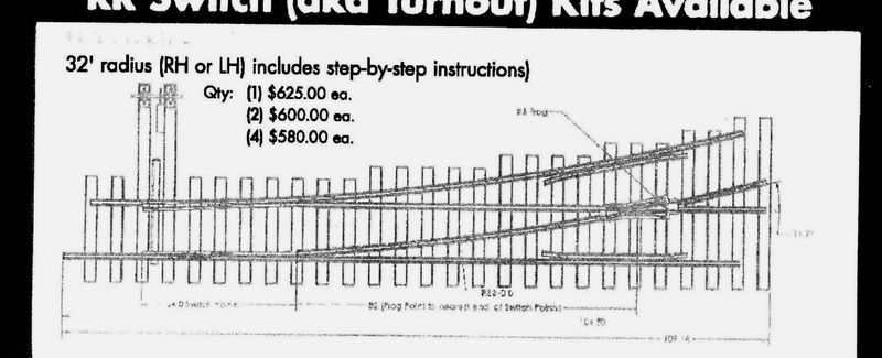
To help in the loading/unloading of engines and rolling stock onto the track, I have a “lifting rack”. This rack goes all the way down to “ground level”. I have contemplated either buying a RTR turnout in this gauge or getting parts from various vendors and building one. RTR is expensive…upwards of a thousand dollars each! Building from parts available is only for those with experience doing this because of the geometry needed to make this size work. But a company in Kent, Ohio (EP Plastics aka Accutie Rail System) has designed a system of plastic ties with molded tie plates with screw holes in place and the track is automatically “self-gauged”. These are the ties I used on the track panels. Recently they have added Turnout “Kits”. ALL items are included in the price: ties are pre-drilled by a CNC mill for the rail, frog and guard rails. ALL rail components are CNC drilled and numbered, steel points are CNC milled to the size turnout you want and predrilled to attach to the switch throw bar and to attach to the closure rails (BOTH straight and curved). The points come in #5 (32 ft. radius), #7 (62 ft. radius) or #9 (102 ft. radius). The frogs are exactly like the prototype and STRAIGHT through. The really nice thing about these turnouts is that the company will sell ALL or part of what you need. This really makes these turnouts well affordable. By the time I complete this switch, the cost is less than $225 including ties, frog and points, SS screws for mounting ties and all prints to build it. I will be doing the milling of the closure rails, straight stock rail and curved stock rail. I will be using individual plastic tie plates to establish gauge. AND I will be bending my own rail (code 1000 aluminum rail with a 15/16 wide base.

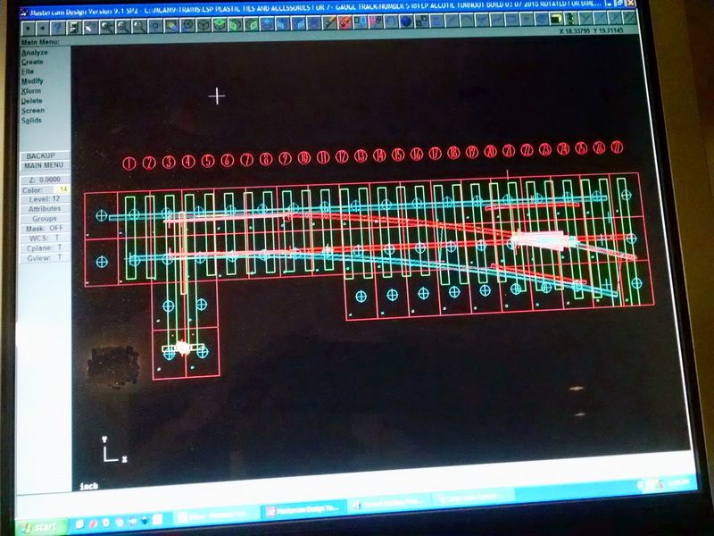
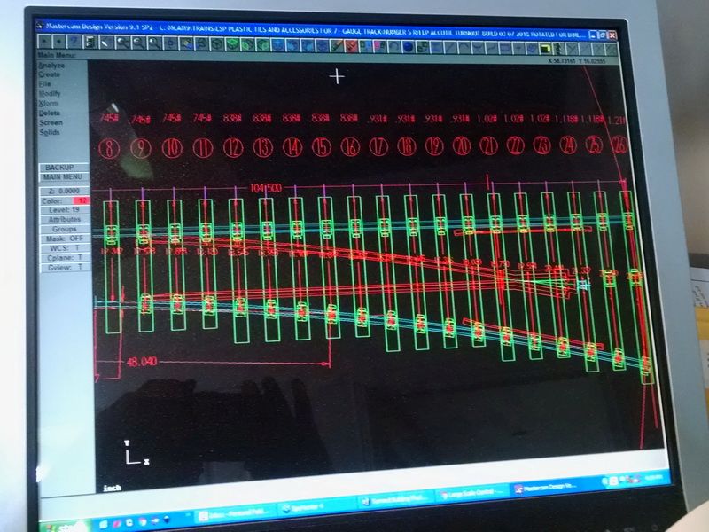
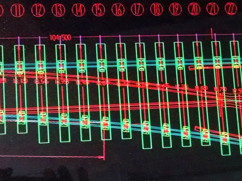
First I did a cad drawing of the switch with all components in place including ties, holes to be drilled in the ties, steel points using dimensions from their prints. This is a plus, because the geometry is figured out for you!

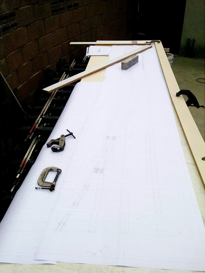
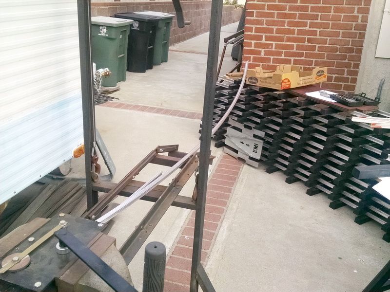
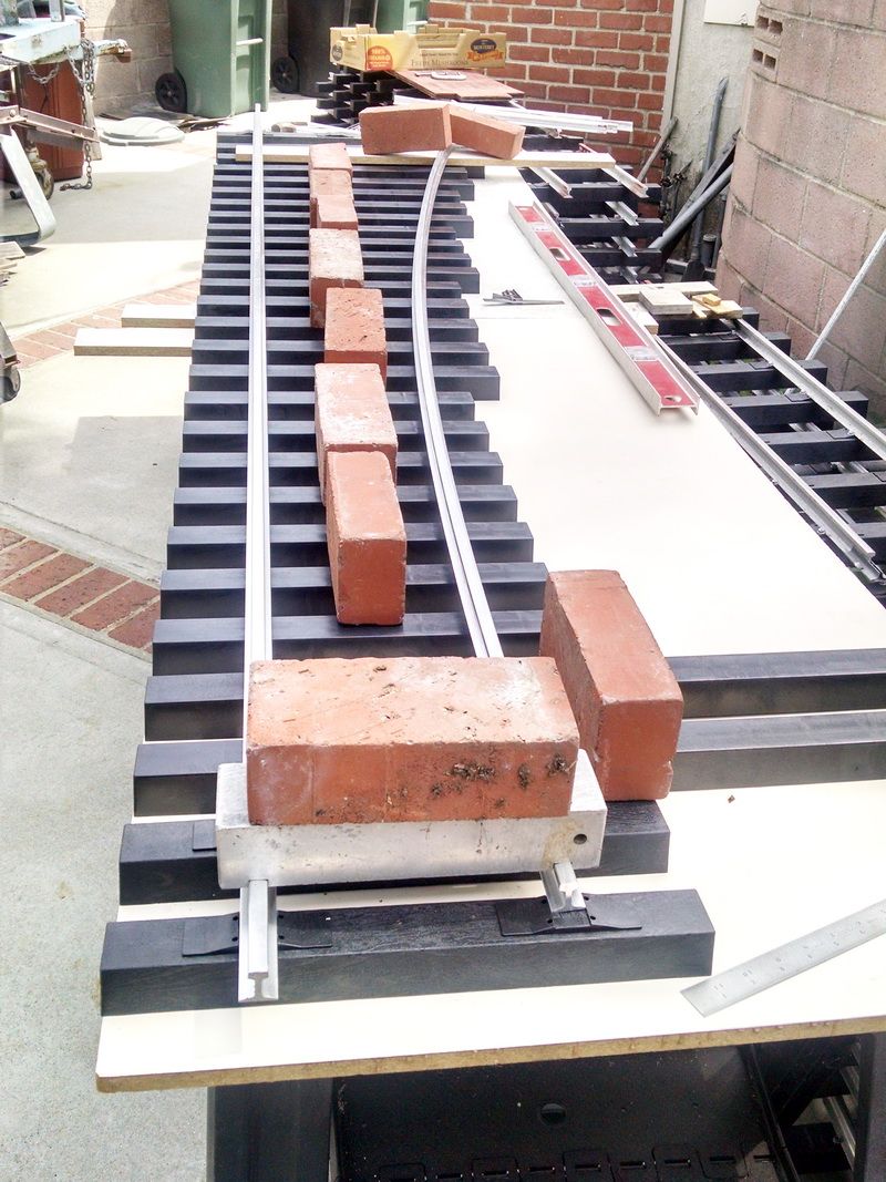
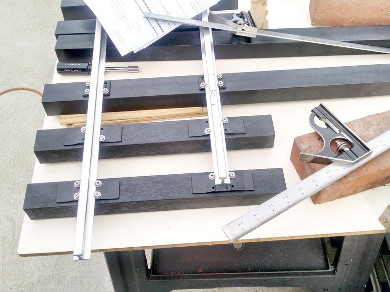
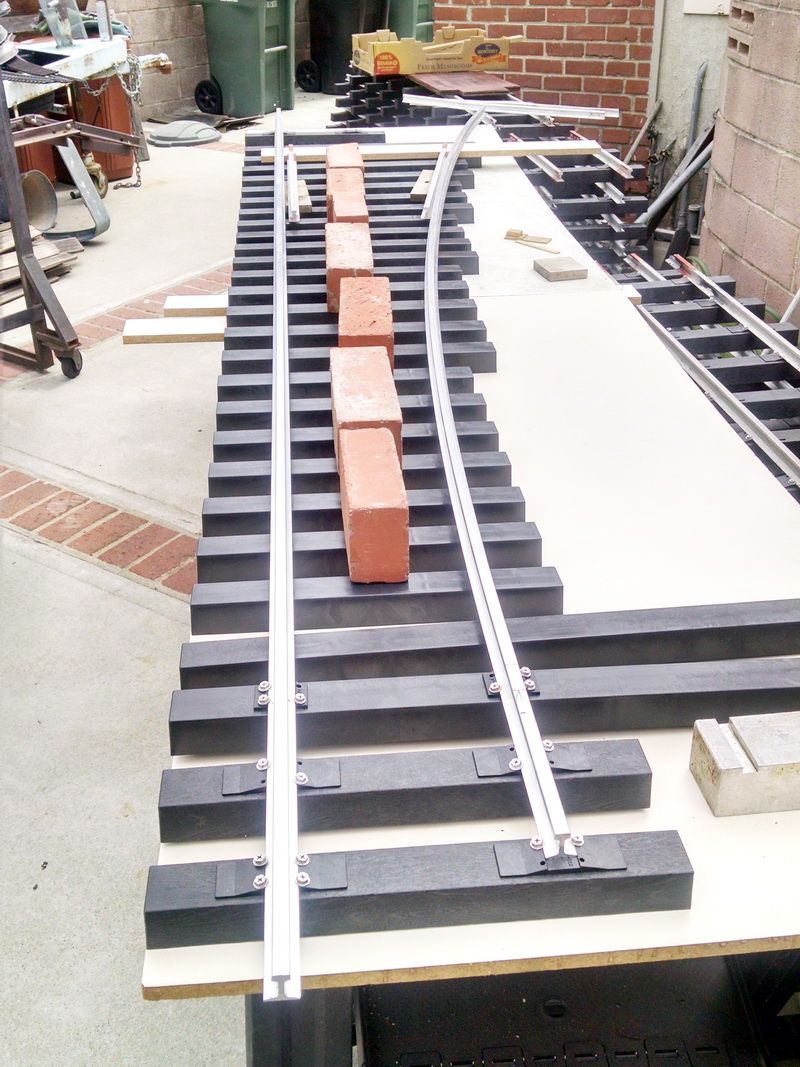
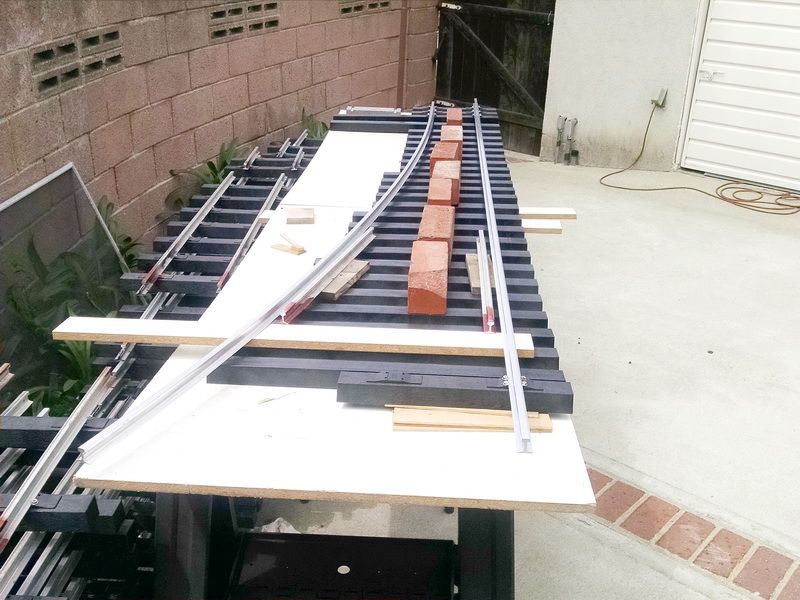
Because I have the full size cad drawing, I can now make a FULL size accurate plot (using PLOT in the software) and make an actual template to layout the turnout and fit pieces into place. In the photos below, this is what I have done. You can see the frog here in the foreground and possibly the points on the opposite end. Also shows the ties placement. BTW, the ties are on 4 inch centers.

I have a friend who just happens to live within four miles of the West Coast distributor for Accutie Rail Systems in Minden, Nevada (Allen Models of Nevada). So my shipping cost is ZERO. Another plus. My friend made a delivery here last Saturday and we laid out the ties, rail and switch stand to check for size of this large switch.

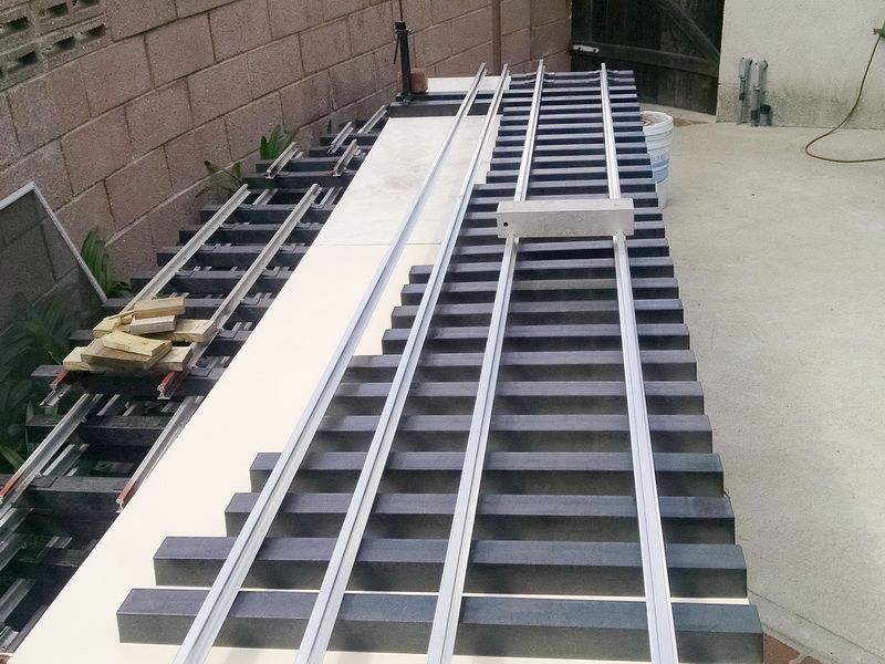
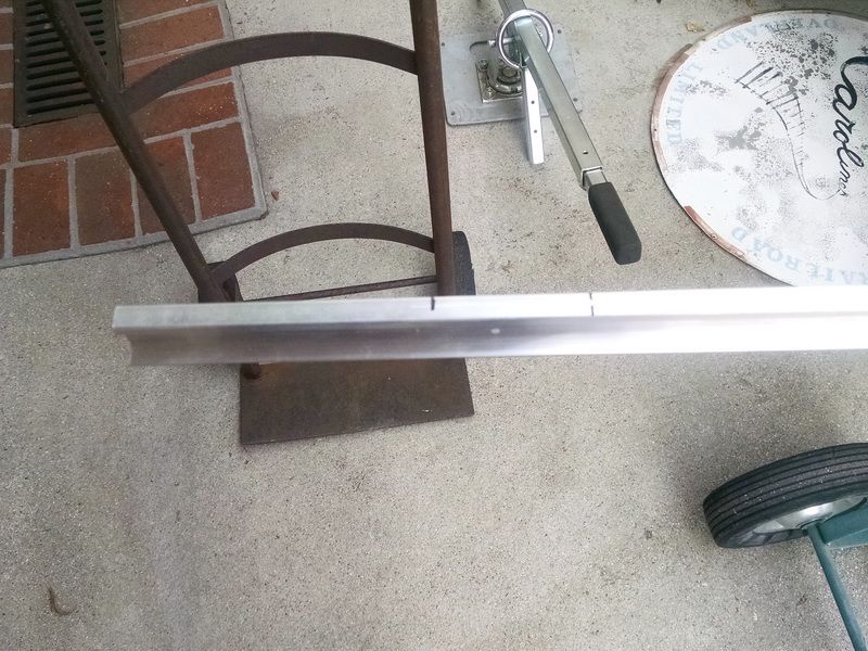
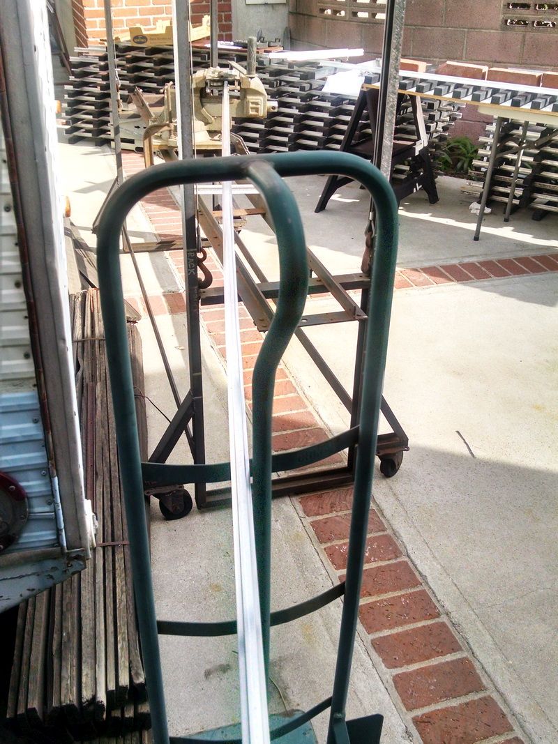
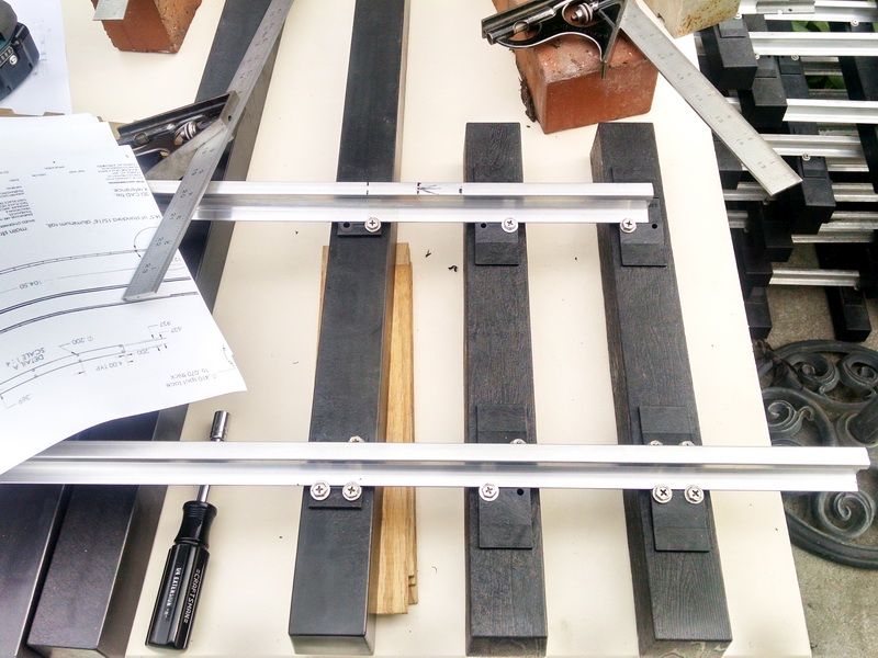
Forty feet of West Coast rail. The two outside rails will be the straight and curved stock rails. The two middle rails will be the material for the straight and curved closure rail.

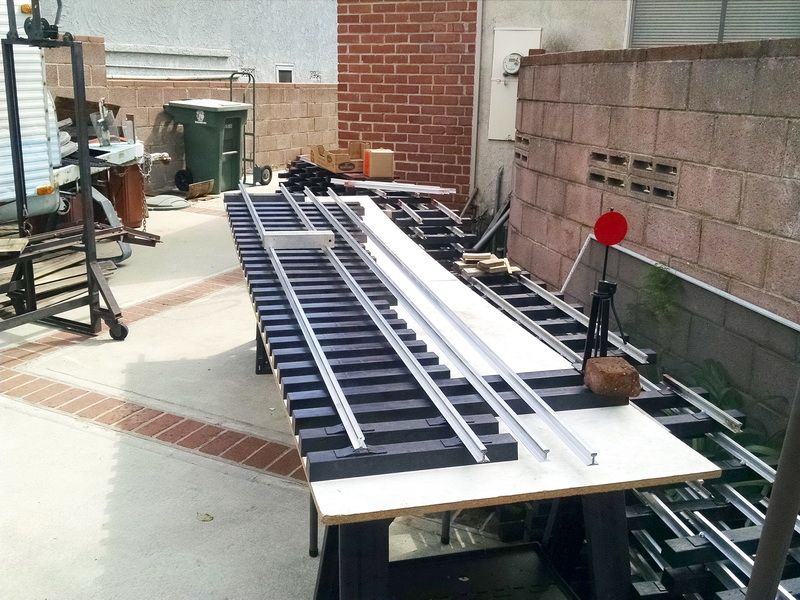
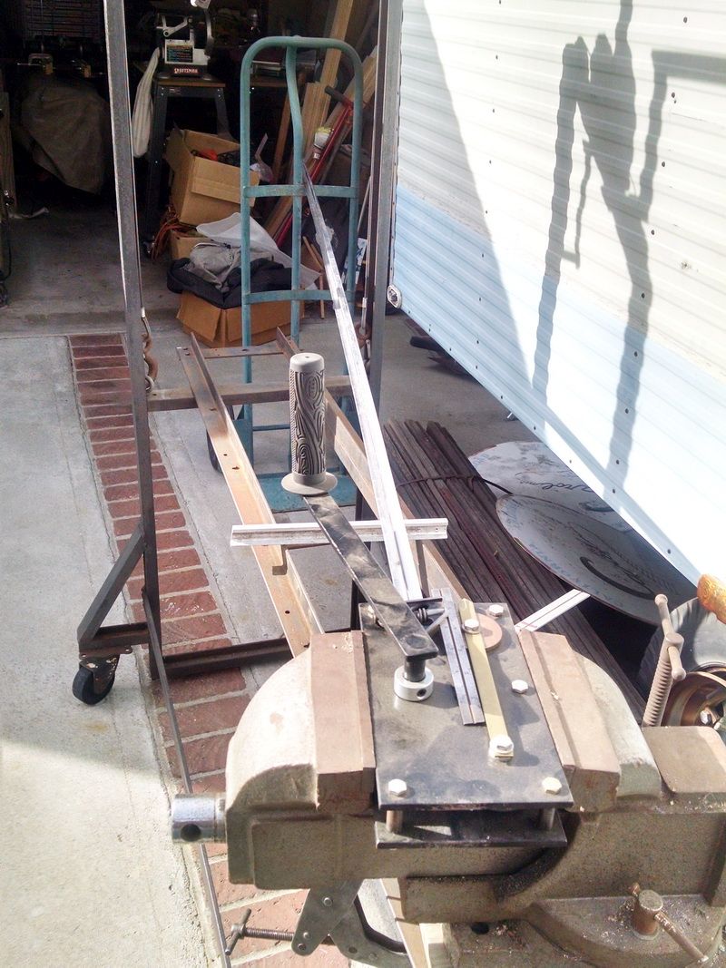
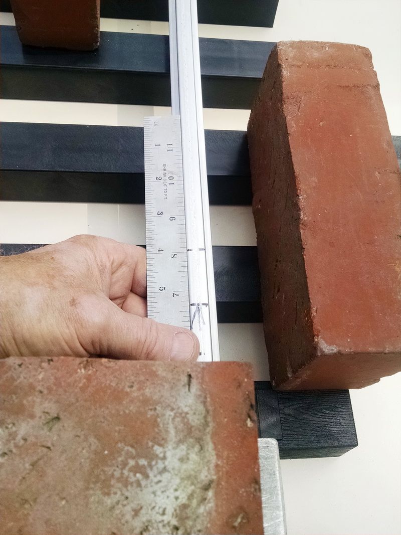
The 2-1/2 square aluminum block is one of my two track gauges. 1/2 inch wide groves milled into the block that fits over the rail head. The 16 inch tall switch stand is on the right and will be mounted on the two 30 inch long plastic ties.

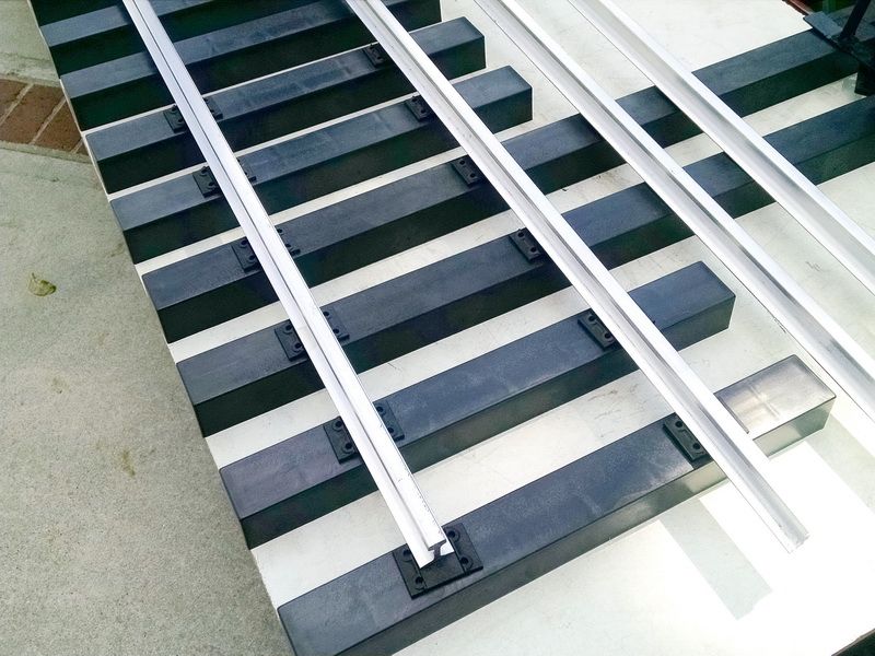
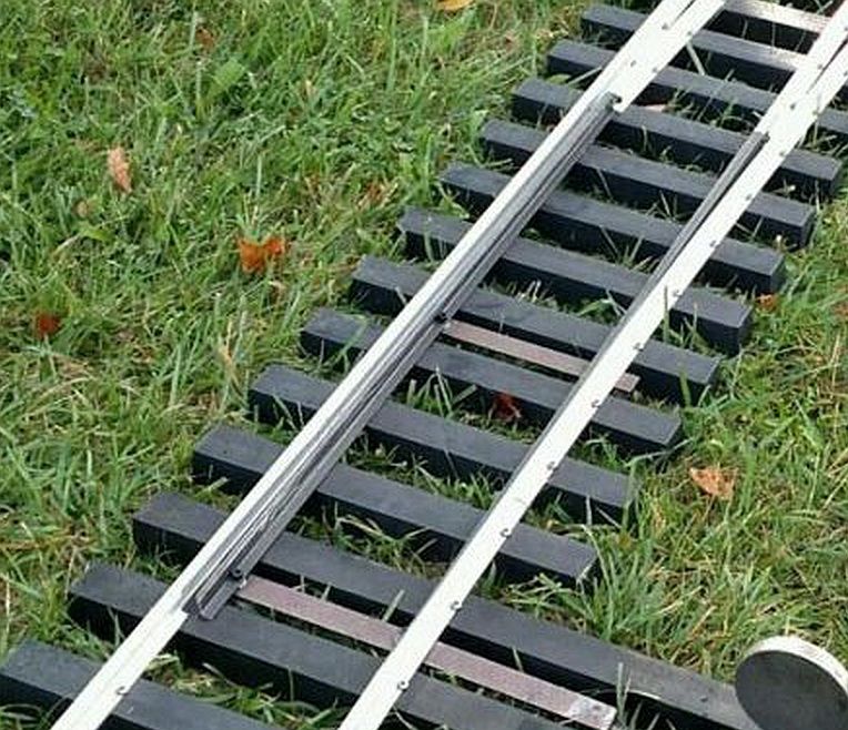
You can see the individual plastic ties plates set in place temporarily. The ties in the foreground are 2X2X16 inches long. UV protected. Many clubs in the US now use these…they last “almost” forever, impervious to rot, weather.

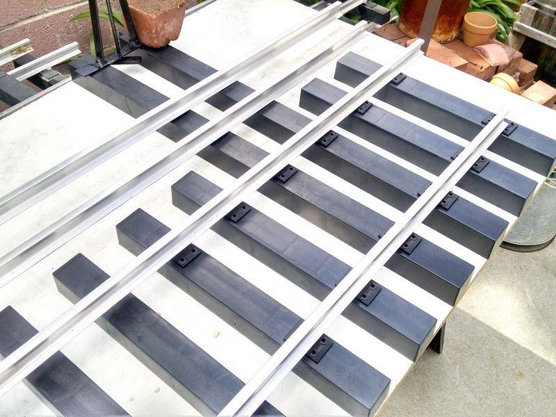
Another shot of the ties and tie plates.

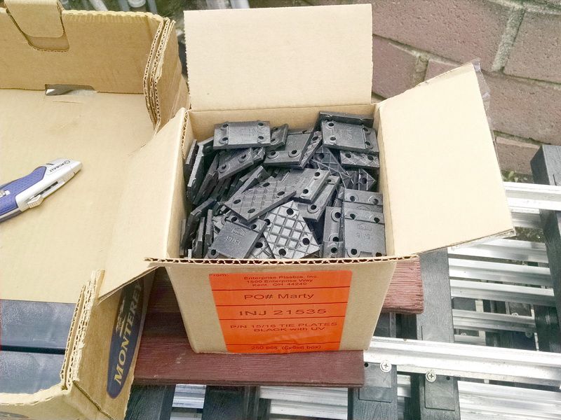
Box of 250 plastic tie plates…dime a piece (very reasonable).

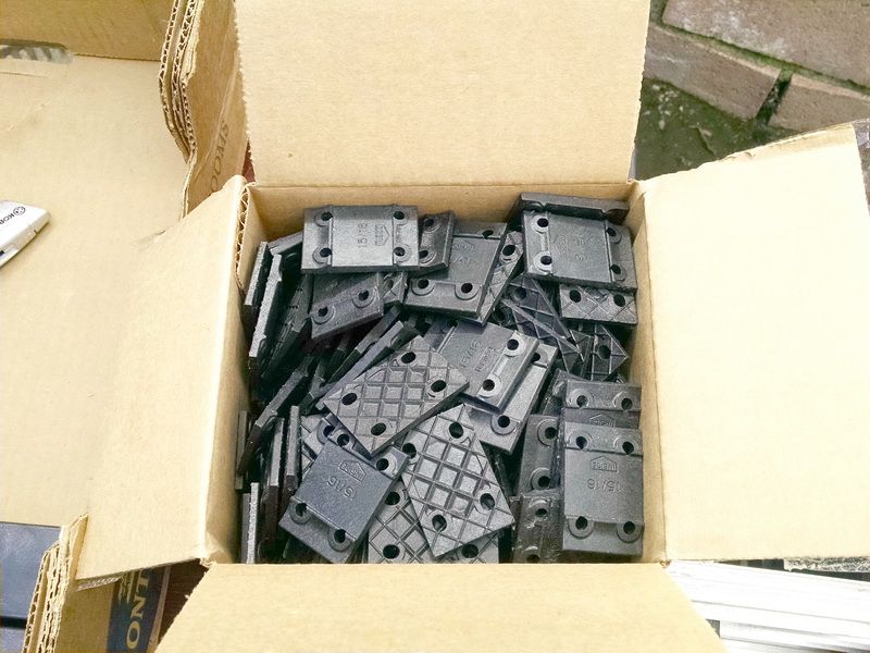
Four holes molded in to each plate. The base of the tie plate is “canted” inward toward the center of the track panel (per prototype) 1-1/2 degrees. As you can see, all that information is engraved on the plate. You can see the 15/16 web width and the arrow and note showing the “inside” of the rail. Almost “foolproof”.

Fully machined steel points. I will receive the points and frog in my next shipment. NOT in Nevada yet :(. But I have quite a bit of work to do in the meantime…cutting and bending rail. Then machining the notches in the stock rails for the ends of the points. Build continues…

Cool project Gary, bet this had you scratching your head a little bit.

Rick Marty said:

Cool project Gary, bet this had you scratching your head a little bit.

Rick,

The software makes all the difference in the world :). I have never built a turnout of any kind in ANY scale…this one will definitely have a big learning curve. Because of the expense of the materials, I can’t afford any mistakes with this one. The mating portions of the stock rails and the steel point ends is kind of critical. The full size plot makes easy work of that! The straight stock rail has a .52 degree taper to the point end and the curved stock rail has a 1.02 degree taper leading to the point end. And these are all moving parts!

Prints come on 8.5X11.0 sheets of paper for reference dimensions. The above prints are for the straight stock rail and the curved stock rail. I will machine these on my milling machine. Easy material to cut…6061 T6 aluminum. 1 inch tall and 120 inches long.

How heavy is this switch going to be ?

Thanks for this write-up ! (https://www.largescalecentral.com/externals/tinymce/plugins/emoticons/img/smiley-laughing.gif)

Interesting…and impressive.

Sean McGillicuddy said:

How heavy is this switch going to be ?

Thanks for this write-up ! (https://www.largescalecentral.com/externals/tinymce/plugins/emoticons/img/smiley-laughing.gif)

Sean,

So far the weight is a “guesstimate”. The ten foot track panels are around 27 pounds each (same kind of ties that are used in the turnout). I have been told by Accutie Rail that this one would be around 100-110 pounds. It’s a “shade” over 9 feet long.

EDIT: I talked with a few people today who have already built several of these turnouts for their home 7-1/2 inch railroads and they were saying that they doubted the factory’s weight estimate of this #5 switch would be this heavy. Now the #9 switch could very easily be heavier than this because it is over 16 feet long and the points are over 36 inches long. I weighed all the components that I have and believe this switch will probably come in at about 70-80 pounds.

Just a tad heavier then the Atlas snap track we played with as kids.

Continuing the build of my #5 RH turnout…

I again laid all the switch ties out on my building fixture and set the main straight stock rail in place. Then I setup the rail bender to start to bend the main curved stock rail. The radius of this rail is 376.375 inch radius. But it also has a 8 inch long straight section at the beginning of the switch and the start of the machined notch for the points.

The longest mark is where the start of the notch for the points will be. Just a rough dimension now for reference to the rollers in my bender. The last eight inches has to be kept straight. The mark closest to the end of the rail is to reference how far to go into the bender.

Rail bender setup…this aluminum rail is 120 inches long. It will become the main curved stock rail with the eight inch long straight section and notch for the point end. The rail bender is at the far end. I loosen the movable roller and insert the straight rail to establish the starting point for the roller on the cam. I tighten the cam and remove the rail. A mark is put on the bender for the starting point of the radius and then moved about a 1/16 of an inch to make the first bend.

This is the bender end of the setup… Large crank to rotate the center drive roller. The farthest roller is on a cam and adjusts to make the proper bend. The brass pointer is a reference to the closest stationary roller position and the roller mounted on the cam.

Completed bend. 376.375 inch radius. Tomorrow I will layout the 1.02 degree angle notch and setup the rail on my milling machine table to precisely cut the notch.

You need a bigger yard…(https://www.largescalecentral.com/externals/tinymce/plugins/emoticons/img/smiley-wink.gif)(https://www.largescalecentral.com/externals/tinymce/plugins/emoticons/img/smiley-cool.gif)

Gary,

Just eye-balling that bend it doesn’t look a bit over 377.291, musta sprung back on ya(https://www.largescalecentral.com/externals/tinymce/plugins/emoticons/img/smiley-tongue-out.gif)

Rick Marty said:

Gary,

Just eye-balling that bend it doesn’t look a bit over 377.291, musta sprung back on ya(https://www.largescalecentral.com/externals/tinymce/plugins/emoticons/img/smiley-tongue-out.gif)

Hey Rick,

Ha! Ha! Happy Easter buddy…When I first got the prints for this switch, I had to laugh at the tolerance on the dimensions. They were definitely drawn in some cad program and whoever did them just never bothered to change decimal point setting! +/- a tenth of an inch would have been more than close enough :). When I checked the arc this morning, it IS a little sharp, but this stuff really flexes quite a bit (on a ten foot chord, the height of the arc can vary a 1/2 inch or more. I’ll just run it through the bender after a slight change to the “cam wheel” :). When you don’t get it close to the radius you want, the rail this size has a tendency to put a lot of strain on the track screws and the tie plates. But this build has been fun so far. The milling of the point notches will be interesting. The mill table is ONLY 30 inches long, but the rail is 120. I’ll set it up using a couple of ten pound angle plates fastened to the table and clamp the rail to those. Indicate the taper angle in and cut with an end mill.

Ken, I DO need a bigger yard. But the weather out here now is great for having the shop outside and in the driveway! BTW, the temp was 81 yesterday!

Continuing the number 5 turnout “build” on Easter Sunday…

Did a little “tweaking” (tweaked the bender a little) to the main curved stock rail…much closer this time. Positioned on the ties and checked gauge. Looks good and now setting up on the milling machine to cut the point notch snd angle. Also going to mill the notch in the main straight stock rail. Should take the remainder of the day. You can see how the sheer weight of this large rail has a tendency to want to “tip” until you fasten the rail to the ties with the tie plates. I use 8 pound brick as a weight to alleviate some of the tipping. The rail is NOT twisted. The bender keeps the curve from twisting by holding between two steel plates with very little clearance top and bottom. About .020 clearance total…0.010 top and 0.010 bottom. Just slips through.

Checking the eight inch straight lead in section for the point notch.

The diverging end of the turnout. I use one of the 16 inch ties with the molded tie plates to check gauge (the small tie in the foreground).

Image result for wow smiley

Phonely…

If only I had the space, money, time, and permission…

Late yesterday, I started to make the setup on my milling machine to machine the notch and tapers for the switch points. But because of the amount of spring and flexing in this aluminum rail, I literally went “back to the drawing board” (my computer cad software.

“The drawing board”

Hopefully in this closeup, you can see that I have the dimensions on my drawing of this switch. These are taken right down the center of each tie to the inside edges of the rail head. This establishes my coordinates for the curved stock rail. As I progress down the curved rail, I will place tie plates and check the gauge distance from the drawing to the actual rail and fasten the tie plates in place one by one. The curve will then follow the curve EXACTLY like the drawing. Almost fool-proof. Beats making check gages.

So in the meantime (while waiting for the frog and switch points to be delivered), I started to fasten the tie plates in place and get the straight main rail and curved main rail installed. Just loosen the track screws and reomove each rail to machine the notch and taper on the mill.

The ends are staggered per print dimension and screws installed. On the switch, I’m using four screws per rial on the tie plates for added strength. On a single track panel, I use only two of the four holes. The panel track needs to be able to move for expansion/contraction. Notice in this particular photo, I am using a tie with the molded tie plates in place. This way I get the 7-1/2 inch gauge correct and no chance for gauge to move. I’m also using a molded tie plate tie on the second position nearest the notch for the switch points. Two more track screws have to be added to that tie. There are only three track screws on the third tie (30 inch length for the switch stand and throw bar and also the area where the notch and taper start for the switch points. Lot going on in this area.

Another view of this end. Note the print in the upper left corner. Shows the notch and dimensions.

Looking down the length of the turnout. I have the two guard rails material in the rough position. The rails are a little over 20 inches long when completed including the angles on each end. Also the curved guard rail has to be bent to the correct radius first.

Photo of the diverging end and the two guard rails. Bend these tomorrow and cut to finish length. Then bend angles on each end and fasten into place with tie plates.

Should be able to cut the rail stock for the two closure rails between the switch points and the frog tomorrow. Machine the ends where the points meet and leave it a little long where it meets the end of the frog. All the machine work is on the points end. Not much machining on the frog end except for screw holes for the bolts to fasten the casting and the rail.

Gary, I am enjoying watching this build progress. Thanks for documenting and sharing.

So you are doing the curve through the frog?

Also the curved guard rail has to be bent to the correct radius first.

Gary this looks great.

Can you remind us How old are you again ???

Fascinating to see develop and materialize.

David Maynard said:

So you are doing the curve through the frog?

Also the curved guard rail has to be bent to the correct radius first.

No…the frog is STRAIGHT just like the 1:1.

Reread my last post regarding the guard rails. :slight_smile: