Large Scale Central

South Fork Sawmill

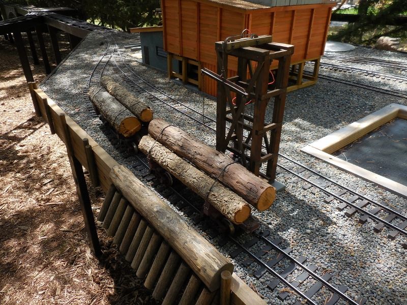
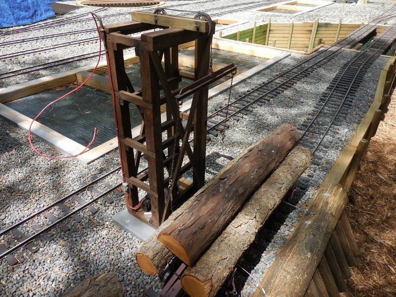
Ken, those slabs, mill blocks, you see stacked in the pictures above are especially good wood, cut offs from logs that were imported out to the west coast frm back East at great expense, to somebody(https://www.largescalecentral.com/externals/tinymce/plugins/emoticons/img/smiley-smile.gif)

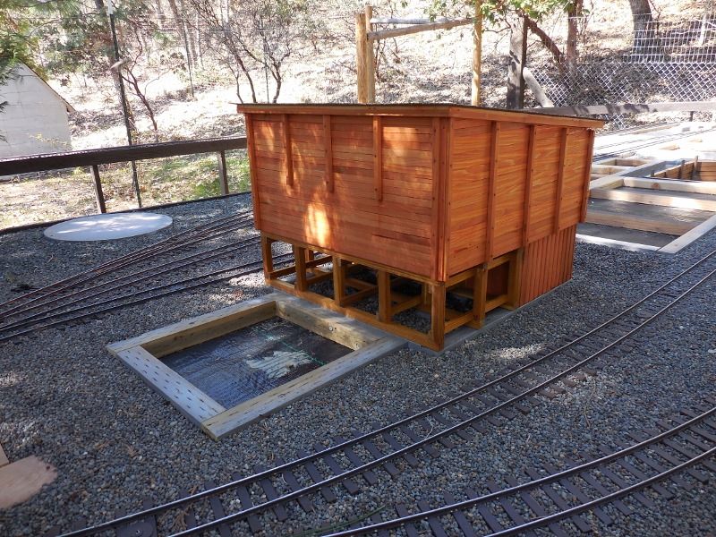
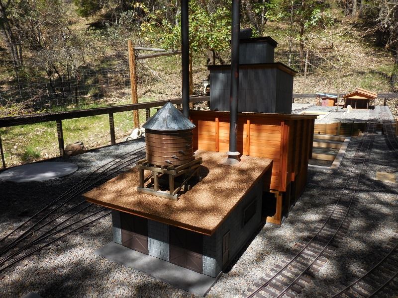
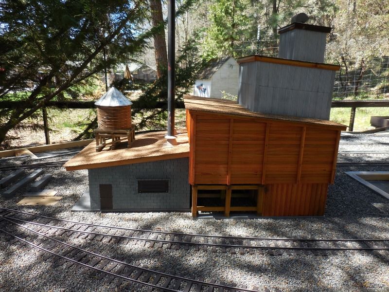
The next structure I tackled was the fuel bunker and main boiler building for the sawmill complex. This building and concept are based on the prototype at the Hull-Oaks sawmill in Monroe/Dawson, OR. The sawdust and planer shavings are moved to this bunker and fed to the boilers as there main source pf fuel. Any excess is moved on to the Tee Pee burner for disposal, the slab wood, as already discussed, is sawn into lengths and used in the other boilers and company housing stoves.

Hull-Oaks still uses steam to power the head rig but electric is used for most everything else. The prototype structure was built in the 1920ā€™s and is still used. Bill at Western Scale Models did a detailed plan set for the entire sawmill back in, I donā€™t know, maybe the 90ā€™s and here is the boiler/fuel bunker drawing.
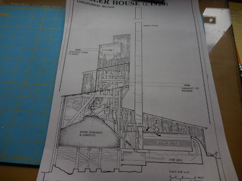
A very cool structure, as usual, I didnā€™t build an exact model but followed the concept and came up with something I liked. Of course I did a complete card board mock-up to determine size and layout before starting construction. The construction material is Western Red Cedar fence boards, recycled house siding and metal from the Clydsdale metal works.

Here is a video (home movie) of the Hull-Oaks sawmill showing the structure Iā€™m talking about. At about 1:21, 5:13 and 6:08 you can see the structure we are talking about. At between 5-6 min. in you can see the sawdust being fed into the boiler fire box. There are lots of videos about this mill on YouTube but this one shows the building as good as most.

https://www.youtube.com/watch?v=VhOSE8jUw68

So here we go, I didnā€™t take very many construction pictures of this project, I got wrapped up in the building and completely forgot about documentation for the most part, so we will see a few disconnected shots of the progress.

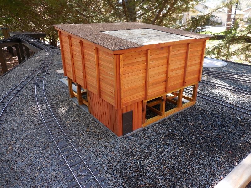
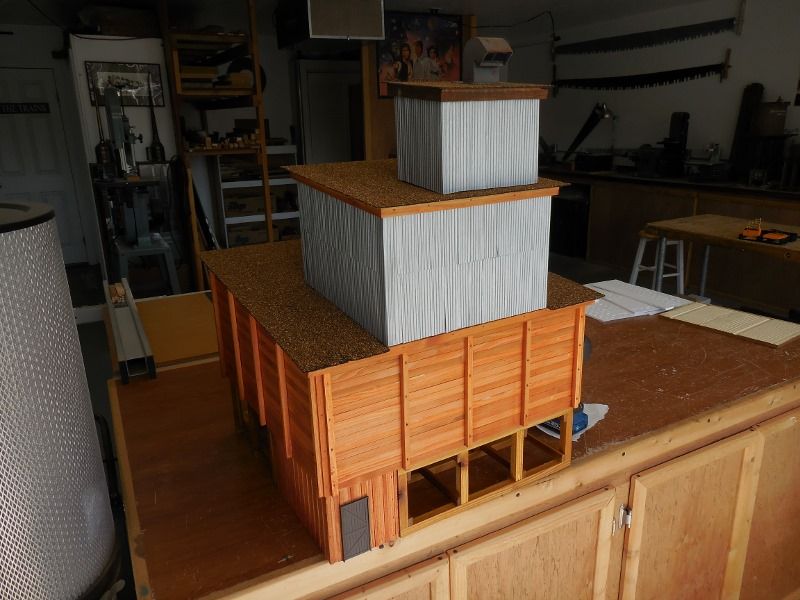
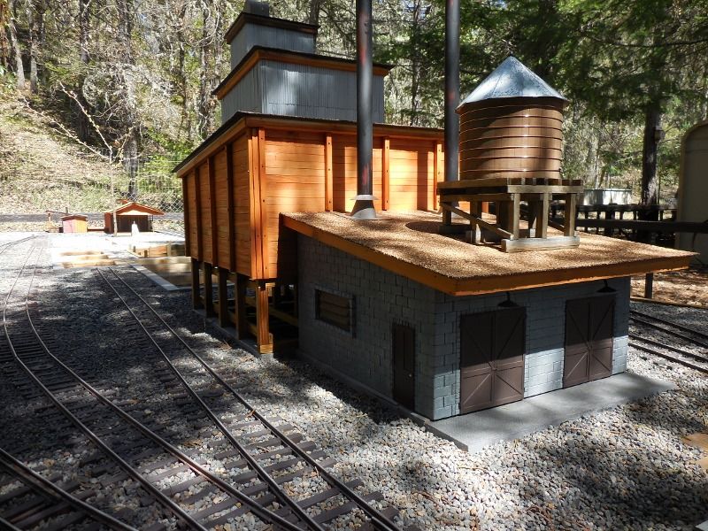
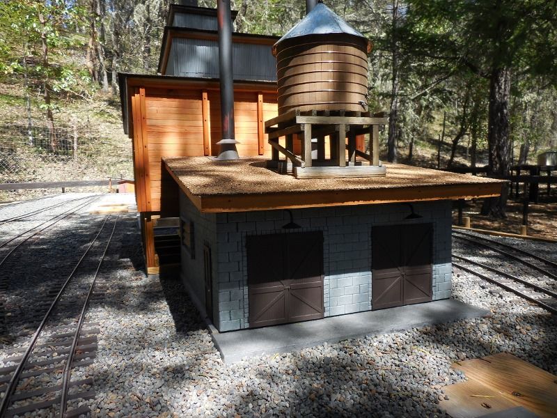
In these shots you can see th basic structure developing, the trestle base with storage room, the fuel storage bin, the equipment room and the cyclone building on top with the gooseneck ventilator on the roof. The building boxes are recycled house siding clad with old growth Redwood stripping or corrugated beverage cans.

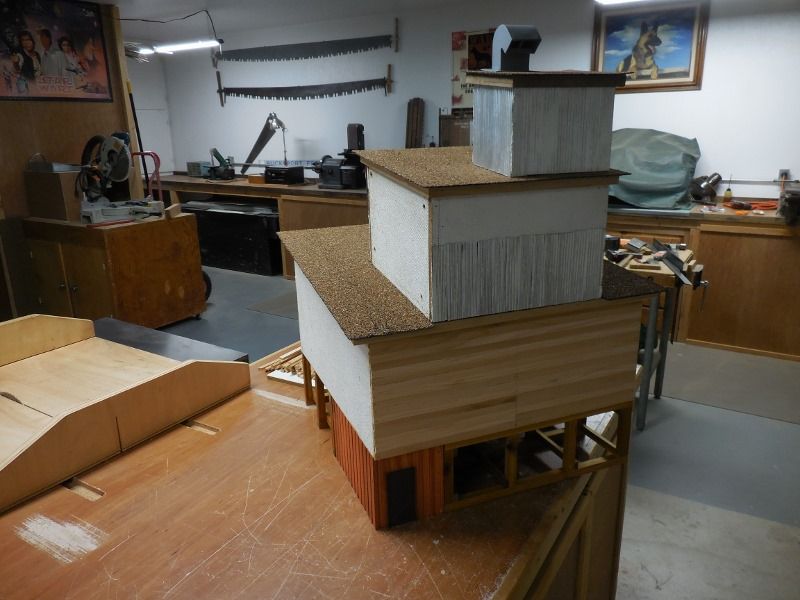
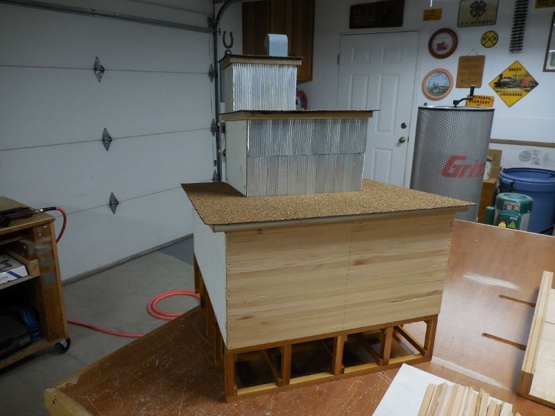
This thing turned out really heavy so it is basically in 3 sections, the bottom trestle section and the bin section sits on that and the roof of the bin and the 2 upper structures are the third section.

More later

Rick

A few more in progress shots.

Test fitting the fuel bin to the building foundation.

All 4 stories completed. I tried something new (to me) on this build, The boxes were built out of used house siding sheet. the Redwood was glued (Tightbond 3) and pinned, but the metal siding was glued on with Vulkem 116 polyurethane sealent. The upside of using it is that it sticks hard to almost anything and creates a completly water proof coating. The down side is that it is thick and takes some care to get an even,thin coat. Also it takes several days for it to cure/harden/dry and things have to be kept weighted or clamped so the parts donā€™t sag or slide around. Even so I am trying it now on a new project and the test pieces are looking really good, more on that later.

Next week we will have a few installed shots.

Thanks for taking a look.

The last of the fuel bin/boiler house pictures, at least until I get the blow pipe and chain chute work done.

All finished and in place, The boiler building is concrete block (scribed PVC sheet). I thought my 1939 era might be too early for block but after a little research I found that they were producing ā€œconcrete masonary unitsā€ as far back as the 1890ā€™s. They have evolved quite a bit since then to become the range of blocks that fit custom applications today.

I added a water tank to the roof because, well just because I could(https://www.largescalecentral.com/externals/tinymce/plugins/emoticons/img/smiley-foot-in-mouth.gif) The roof jacks and storm collars for the boiler flues are made from sheet Styrene and the flues are 3/4 PVC pipe. I know that the building looks like it is leaning to the right in the picture but it really isnā€™t.

A couple more shots just for the hell of it.

I think a few smaller mill projects will come next.

Thanks for taking a look

The PVC sheet you use isnā€™t the same stuff you buy at the big box lumber stores, right? What do you use to scribe lines?

Craig Townsend said: What do you use to scribe lines?

A Rooster Beak ?

Waitā€¦they only make ship lap grooves

Nice job with the details on the roofs: stacks, vents, tanks, etc. Makes a huge difference to have something besides a flat uniformly colored rectangleā€¦

Next we have the log dump or car unloader.

I had limited space between the tracks so had to find some system that would fit and be prototypical. In searching through my old sawmill picture files I found just what I needed, a tower unloader with electric motor and winch. The red wire hanging out the back is/will be the electric line that comes from the main mill building once that gets built.

A log car in place at the brow log in front of the unloader.

The wrappers off and the cables attached for the dump.

A view of the motor and winch setup.

On to the next project,

So, theoretically the operator is standing in the log pond? And it appears that thereā€™s a bridge over an opening for the logs to come into the sawmill, presumably with some kind of chain lift out of the water? Do I have that right?

Iā€™m loving this whole build. So much bigger than I have space for! Enjoying it a lotā€¦

Jim Rowson said:

So, theoretically the operator is standing in the log pond? And it appears that thereā€™s a bridge over an opening for the logs to come into the sawmill, presumably with some kind of chain lift out of the water? Do I have that right?

Iā€™m loving this whole build. So much bigger than I have space for! Enjoying it a lotā€¦

That is correct Jim, at least that is how it will work in my mind, we will see what actually happens a little farther down the tracks. (https://www.largescalecentral.com/externals/tinymce/plugins/emoticons/img/smiley-foot-in-mouth.gif)

Here is a shot of the bridges across the log pond from ā€œstanding in the Bayā€ taken at the open house this weekend.

Next we will look at building the turntable.

Has Richard seen that picture ??

Looks great!

(https://www.largescalecentral.com/externals/tinymce/plugins/emoticons/img/smiley-smile.gif)

Rooster said:

Has Richard seen that picture ??

Looks great!

(https://www.largescalecentral.com/externals/tinymce/plugins/emoticons/img/smiley-smile.gif)

Man, I agree. I remember when Richard first built the extension that utilized that bridge. I thought his scene was awesome. Yours does it justice too!

Thanks guys, yes, Dick was the first to see pictures of his bridge installed here(https://www.largescalecentral.com/externals/tinymce/plugins/emoticons/img/smiley-laughing.gif)

As always Rick Your models are looking very nice

Dennis

The turntable at the mill site was built with a 32 inch bridge and a 2.5 inch deep pit. I laid out the circle on paper and divided it into 24 segments, only one quarter of the circle has to be developed, to give enough pattern for sizing the segments. After laying out the pattern in pencil I free handed in the lines with a Sharpie so they would show better in the picture. So I only had to cut 24 blocks of Redwood then score them with the bandsaw to represent plank lines, no big deal except I hate repitition.

The pit was framed into the table and a piece of 1/2 inch cement backer board was used as the pit bottom. I painted the exposed pit bottom with gray FlexSeal to give it a nice water proof finish then scribed my circle on it for the blocking. This turned out to be a major mistake. Did you know that Liquid Nails, and any other adhesive I could lay hands on will not stick to Flex Seal(https://www.largescalecentral.com/externals/tinymce/plugins/emoticons/img/smiley-cry.gif). Had to think about that for a while.

Checking the fit and layout of the Redwood blocks after ripping down on the table saw and angle cutting on the chop saw, the plank lines havenā€™t been scarffed in yet.

More later, thanks for taking a look.

Rick

After turning the cement board over I was able to get all the block segments glued in place and check the bridge for clearence.

The track in place and the gravel fill added, ready for a coat of FlexSeal now.

More turn table adventures.

I used 1/4 inch Sintra to make a couple of center washers to raise the bridge up to required height and mounted a couple of rub blocks out on the ends so it wouldnā€™t tilt end to end as the loco moves.

The gray FlexSeal has been painted in and the pit is finished.

Once again the FlexSeal bit me on the butt, the rub blocks wonā€™t rub on the FlexSeal they just hang up and bounce along when trying to turn the bridge. I have used the rub block method on turntables before with no problems at all, now I know that it doesnt work on the rubber sealer. The solution I came up with was to notch the ends of the bridge back about 1/2 inch and mount a rubber model aircraft wheel on each end using a finish nail as an axle. Simple and works super smooth and you donā€™t see the wheels under the bridge.

Early morning and turning olā€™ #7, the yard hog, getting ready for the days work. I have had #7 since way back in the day and she is still track powered but has upgraded trucks. She hasnā€™t turned a wheel in about 7 years but that is about to change. She is scheduled for Battery/RC upgrading very soon maybe even the next project.

Well that is all for the turntable build, the next building will be the box factory.

Thanks for taking a look.

Rick

1 Like