Gary,
It doesn’t look like your using a quick change tool post
What are your reasons for that??
Rick
Gary,
It doesn’t look like your using a quick change tool post
What are your reasons for that??
Rick
Rick Marty said:
Gary,
It doesn’t look like your using a quick change tool post
What are your reasons for that??
Rick
Hi Rick,
Most of the tooling that I got with this lathe was the old Armstrong left, right and straight holders with the typical post and circular wedge setup. Biggest tool bit I can put in these is 1/4 square.
Reason…COST :)…some of the really nice “quick-change” products now are very pricey and I am pretty much old school :). I would dearly love to have a “Quick-change”! As you can see, I “adapted” an old tool holder to this small lathe (Atlas/Clausing 12 X 36) about 35 years ago. This holder is from an old 20 inch lathe and was part of some “junk” our old die shop was throwing away. Made a new adapter for the Atlas compound. With this holder, I can use 1/2 and 3/4 “sintered carbide” lathe tooling. I have so much of that tooling after 43 years in the trade (some even brand new in their boxes yet!) A dozen in each box. That cost today would be prohibitive and these are all American companies that have seen gone out of business. OR have been driven out of business…you know what I mean :)!
Just wondering about your reasons. I figured a man with your background would have some solid reasons.
I have noted that the quality “quick change” posts are very expensive as you said. Plenty of cheap stuff available though(http://www.largescalecentral.com/externals/tinymce/plugins/emoticons/img/smiley-foot-in-mouth.gif)
I have thought about getting one but then I think of the down sides; cost is a factor of course, and then on my Chinese lathe it would be like a diamond in a goats a–, if you know what I mean. But mostly I don’t do enough lathe work or do it fast enough to require a “quick change” anything(http://www.largescalecentral.com/externals/tinymce/plugins/emoticons/img/smiley-smile.gif)
Loving your post’s on your ride on!!!
Rick
Gary,
Following along here. Probably better than e-mails.
Started to do the work on my mill today. This involves cutting the journal boxes to size and centering the bored hole for the ball bearings. It’s always easier to bore the hole FIRST and then finish the sides last. I setup a steel angle plate and use a series of 1-2-3 blocks to establish the height and use Kant-Twist clamps to hold the journal box against the 90 degree face of the angle plate. I use a small piece of fine sandpaper between the plate and the aluminum block to help the block “hold” better while making the mill cuts. I “tap” the top of the block using a lead hammer to seat the block against the parallel sitting on the 1-2-3 blocks. When these blocks are tight and don’t move, you know you are seated against the blocks with NO gap.
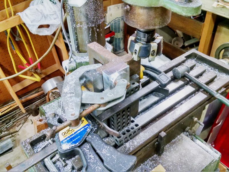
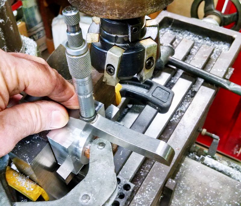
Using my Starrett 6 inch base depth mics, I check the distance from the face I am cutting down to the round “match edge” I turned on the lathe. The round match edge is 1.750 in diameter and the journal box is 2 inches square when finished. So this depth is .125 deep from this face. That’s how easy it is to get the bore EXACTLY centered in the block :).
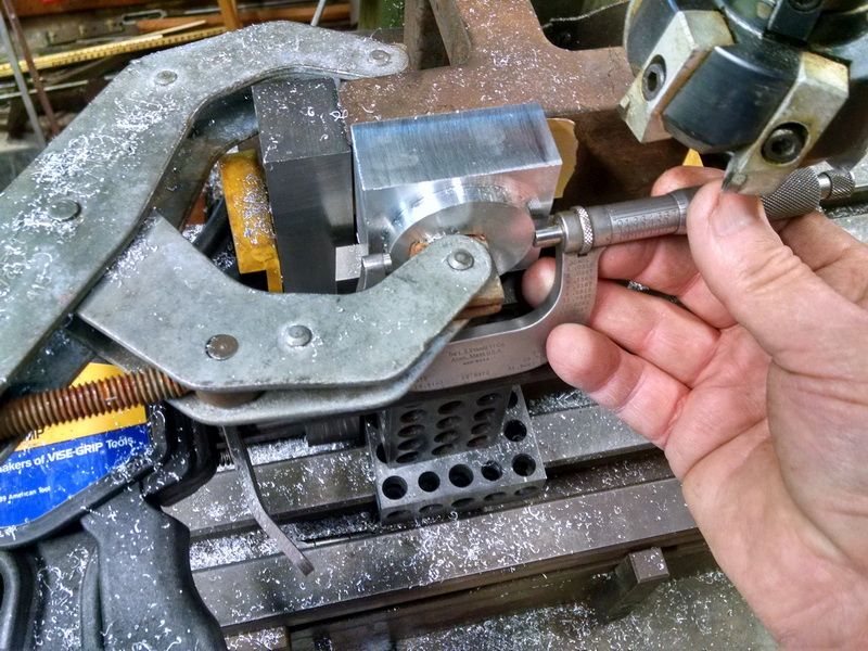
I check the diameter using a pair of 1-2 inch outside mics. It checks at 1.750.
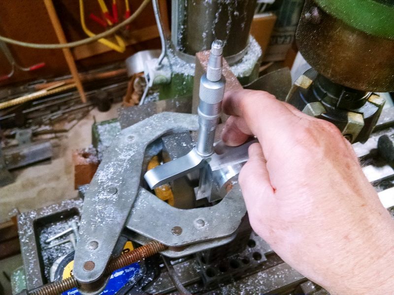
I use a set of 3 inch base depth mics to check the overall thickness of the journal box. This saves me removing the blocks to check that thickness with outside mics. Little “tricks” of the trade.
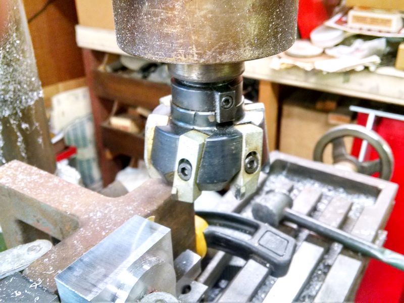
This is the cutter I use to rough and finish these surfaces. This is a 3 inch diameter slab cutter with 6 sintered carbide toolbits mounted. As you sharpen these cutters , you have to adjust each toolbit to cut at the same height. I only use this cutter for doing aluminum and those cutters are still brand new after 35 years! Only used for fine finish work and dedicated to that purpose ONLY.
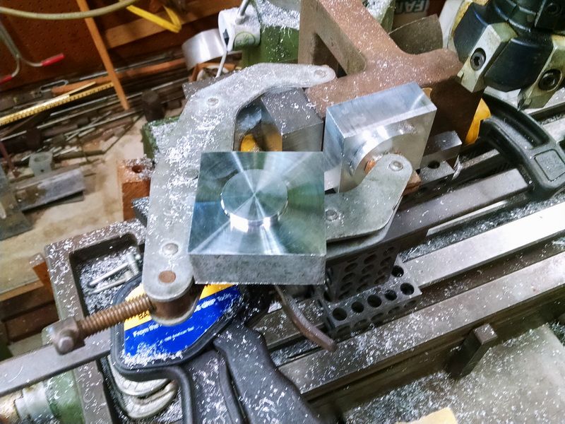
Ready to setup the next block.
Wow, it’s hard to believe 18 months has gone by since I last updated this Eaton Super Husky build. There was the #5 turnout build (seemed like it took forever to finally finish that one). And the build of the new Baldwin P.E. 1600 series box cab electric.
Quite a bit has happened with this Super Husky build inj the past few months. I had to make some financial adjustments to be able to finish this engine. Rich Eaton in Castle Rock, Washington has been producing these neat little engines for 15 years. Well, he decided to stop production on this RTR engines. According to Rich (on his Facebook page), he says it was a good run, but time to hang it up as far as the Super Husky. No more parts would be available and his last engine rolled off the production line a couple of months ago. The last one was Serial #52. When I saw this, I was a little concerned that I wouldn’t be able to purchase some of the parts I would need to complete the locomotive. The big item was the cab and hood structure. I had already decided a long time ago that I would have a local sheet metal vendor do the cab. Cut the window and door openings, rivet holes and cut and shape the roof. I had put out some quotes to get this done in aircraft grade 6061 T5 aluminum. Most vendors thought it was too small of a job and didn’t want to be bothered. Some did come back with quotes to do the cab in 16ga sheet steel, but that would defeat the purpose of making an all aluminum engine for ease of lifting into a SUV. I emailed Rich in July of this year and asked if there was a chance he might still have a “cab kit” still available for me to purchase. He answered back right away and said he would sell me the kit including the side walls, front and rear walls, all the window and door openings cut into each piece, a fully shaped roof ready to mpount, a door to go on the rear wall, window shades bent and shaped to size and ready to mount and the arm rests for each side window. Best part was $249+shipping. I told him to ship one down.
After I worked on my son’s new Baldwin electric today (adding new cab locators shown in another thread here on LSC), I decided to finally open the box holding the cab pieces I had ordered months ago. I assembled the cab late this afternoon to see what it would look like of my Super Husky aluminum frame. All of a sudden, this engine is looking a little larger than I thought. This is cool :). Not a big deal. Photos below:
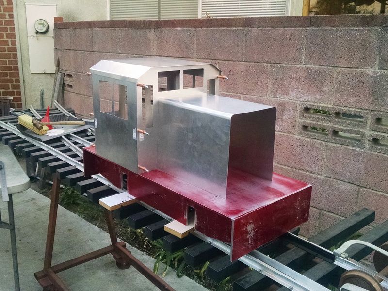
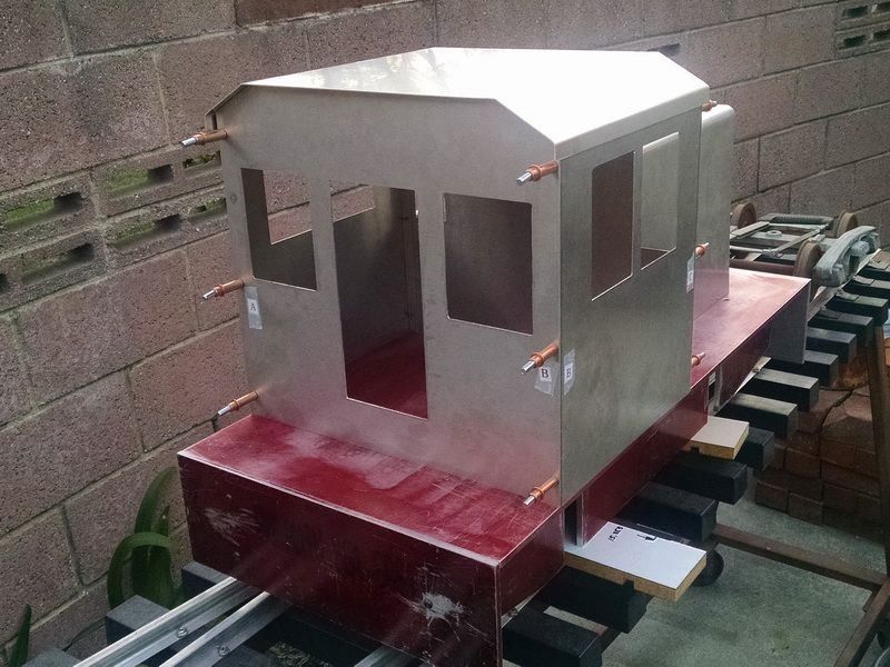
Photo of the assembled aluminum cab, made from .055" thick aircraft grade 6061 T5 aluminum. Eaton uses "pop-rivets to fasten the walls together (I’m using 1/8th inch diameter cleco clamps here using Rich’s predrilled holes). I’m thinking about going to 2/56 Allen button head screws instead. Looks like rivets and easy to take apart for painting, lettering or general maintenance. I’m also thinking about looking a detail photos of old Whitcomb or Plymouth engines for some rivet detail. Might be a nice touch now that I was able to rivet the cabs on our Baldwin electrics without any issues. I’m waiting on a piece of 1/2 inch thick by 10 inch tall by 9 inch wide aircraft grade aluminum plate to machine the custom grill in the front of the hood. My buddy with the CNC Bridgeport mill will be cutting the edges of this plate where it fits into the hood. This way it will be a nice tight “net” fit and NO gaps. I will draw the detail to be cut in the face of the grill including engraving the PLYMOUTH name in the upper section of the grill! It’s really nice to have access to an NC mill for this kind of work. MasterCam will produce the tool paths to make this happen.
Rear wall of the cab with door and window openings. To give you a size comparison, that cab is 15 inches wide and 14-1/2 inches tall. The model is sitting on my just completed #5 turnout with spacer blocks under the frame. For the true clearance when the journals and wheels are install, the space between the rail and the bottom of the frame will be 1 inch (I used 3/4 in this photo).
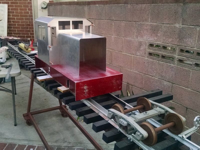
Size comparison with the 1-1/2 inch scale Bettendorf trucks.
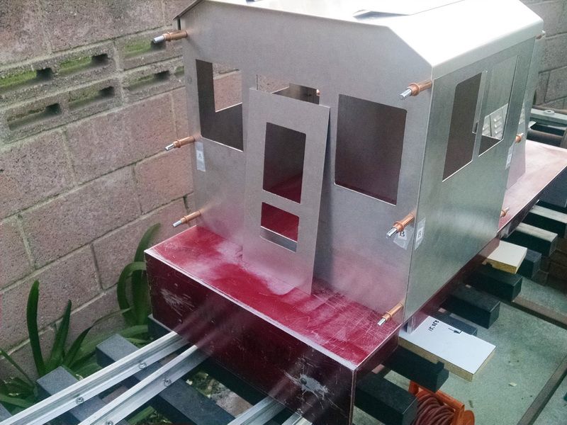
The “faux” door to be inserted behind the rear wall. The idea is that the cab isn’t supposed to be detail. Just a very utilitarian switcher designed for quick and easy loading in a SUV and just for getting out and playing. Not worrying about little details being broken of or lost. Just for “kids” of all ages to enjoy a quick trip around your home or out at the club track.
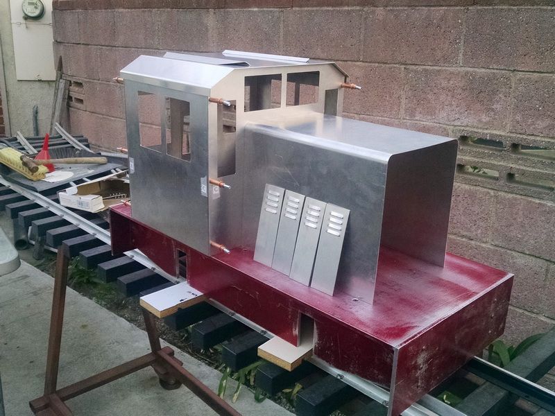
This photo shows the four louvered access doors on each side and the window shades sitting on top of the roof. When these are mounted on each side wall, the long angled section slipps between theroof lip and the side wall and is riveted into place.
That’s all for now. Too many projects…so little time. 
very nice
Gary you need a hobby … with all this free time you have … You lucked out with the kit … (https://www.largescalecentral.com/externals/tinymce/plugins/emoticons/img/smiley-laughing.gif)
Sean said:
Gary you need a hobby … with all this free time you have … You lucked out with the kit … (https://www.largescalecentral.com/externals/tinymce/plugins/emoticons/img/smiley-laughing.gif)
Funny you should say that…my wife says the same thing
I WAS lucky to get the kit. Quite a few folks were surprised when he decided to stop production on this little engine. Those people were doing the same thing as I was (building their own engines and getting the material and machining their own parts). Rich Eaton is STILL in business with his Eaton Custom Engineering in Castle Rock, WA. He just said that production was taking time away from other things he manufactures in the ride-on and HO hobby. He does make some beautiful 1=1/2 inch scale arch bar trucks and other detail items. Also does some really nice HO wig/wag signals and trolley poles for HO traction.
So do you have the prime mover yet for this baby ?
Sean said:
So do you have the prime mover yet for this baby ?
Sean,
As a matter of fact, I do. The man doing the electronics for me has purchased a few motors for other builds he does. The power with be a single 500 watt, 24 volt motor. We had thought about going to two 500 watt motors but the battery capacity of the batteries that will fit under the hood and in the cab just won’t permit that. The single motor with chain drive to the axles and an idler shaft can pull about 11 steel gondolas (empty) on a level track. Pretty strong for only 4 wheels and and a light engine at 150 pounds. There are quite a few videos of Super Husky’s running. This engine will have Phoenix Sound and a RC wireless controller. RC controllers are those used with model race cars. Not tethered. I have talked with folks who use this system and they say the range is about 500 feet. I can literally sit on a bench next to our yard at the LALS club track and do all my switching without being anywhere near the train. The kid’s can handle the couplers and use hand signals :). Many use this system already now in the ride-on scales to control the larger diesels in the 1000 pound range. Just BIG garden railways!! All with full sound and large amplifiers added. Large woofer speakers really can “shake the ground” as they go by :). No room for amplifiers in my critter though.
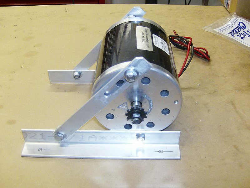
This is the 500 watt 24 volt motor we will be using. I’m told by the man doing my electronics that this motor should provide around 3/4 HP. To give an idea of the physical size of this motor, those aluminum angles for the motor mounts are 1 inch X 1 inch angle.
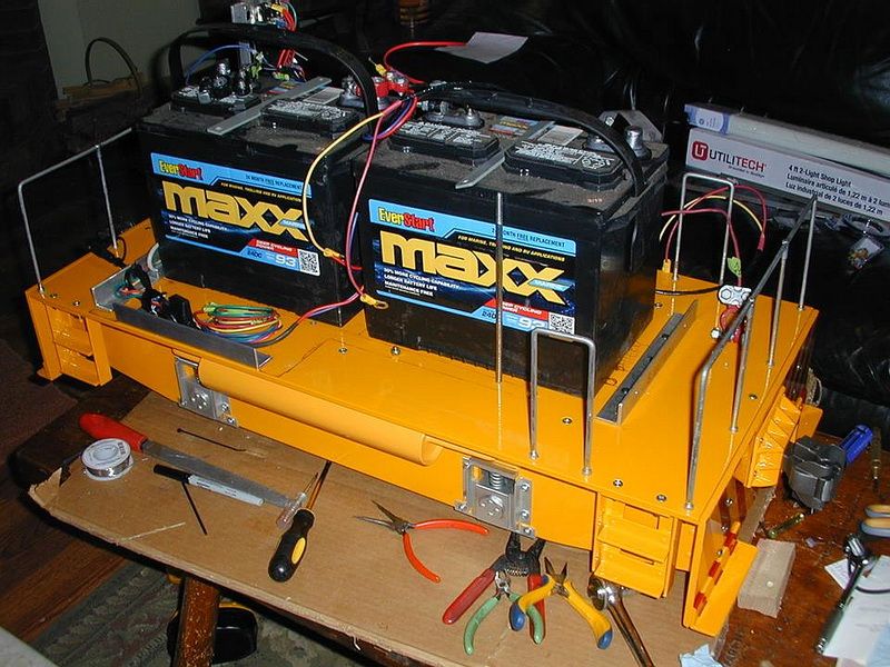
This phoyo shows the two 12 volt batteries that power this little engine. They are both Group 26 size batteries.
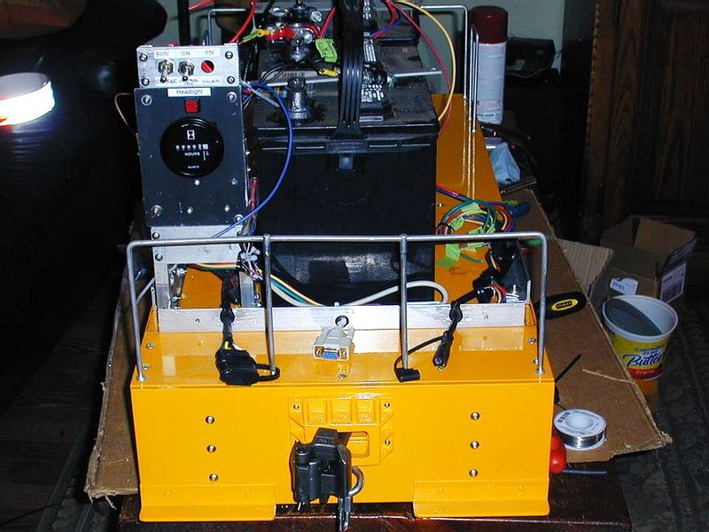
This photo shows the back panel of the electronics. This is the earlier version using a “tethered” cable from the handheld controller box.
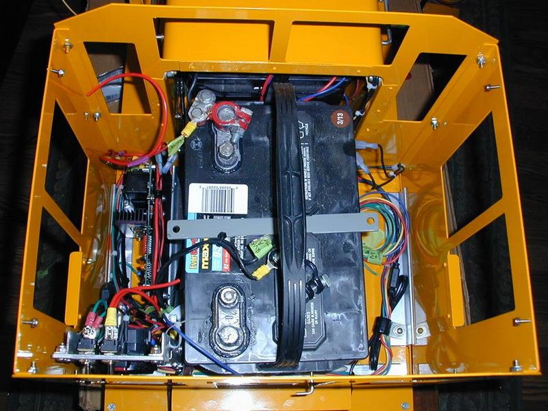
Looking down inside the cab showing one battery and the electrical panel. Not a lot of room.
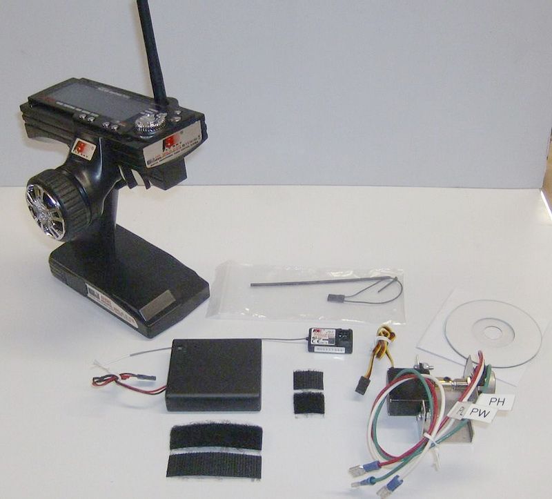
RC wireless transmitter/controller and the small rectangular receiver and motor controller. All available from Amazon for under $50! This doesn’t have to be an expensive hobby. This may even be less expensive than 1/29th!
So it’s probably not gonna have HEP then.
" Rooster " said:
So it’s probably not gonna have HEP then.
Ok Rooster…I’ll bite :).
Hmmm … if you put a ceramic bowl on top of the motor … will it heat it up enough to work as a smoke unit ?
That motor will be working hard …
Video showing a Super Husky pulling 12, 1-1/2 inch scale steel gondolas and two cabeese. Each gondola weighs about 150-175 pounds and the cabeese are probably 125-150 pounds each. Approx. 2200 pounds including the Husky and the engineer. ONE 500 W 24v motor I was told by the manufacturer of these engines to hold the gear ratio around 6:1. I believe the chain sizes are 25 and 35.
Wow, this is serious. The thing even has an hobbs meter.
Sean said:
Hmmm … if you put a ceramic bowl on top of the motor … will it heat it up enough to work as a smoke unit ?
That motor will be working hard …
Like minds and all that … I just ordered an exhaust stack from him yesterday. Has a stainless steel stack and a “rain flapper” :).
David Maynard said:
Wow, this is serious. The thing even has an hobbs meter.
Almost all ride-on engines (gas or electric) have hour meters. Generally to keep track of time in use/maintenance work. These engines clock hundreds of miles (in comparison to thousands of feet with garden railway variety of RR stock). Our club diesels (electrics) have complete maintenance logs for each engine on the roster. So do the club steam engines. Some are small 1-1/2 scale Pacific’s to the larger NG Sweet Creek steamers in 3-3/4 scale. Maintained with the same care that the full-sized railroads did back in the day. When you run at very large tracks like Train Mountain in Oregon or Mill Creek in Michigan, you can accumulate a lot of miles quickly. Train Mountain has almost 45 actual miles of track and Mill Creek is near 5-7 miles, I believe. Our track here in Los Angeles has a mainline run of about two miles for one circuit. All of my electric engines have hobbs/hour meters.
Is it done yet?
Wow, my last post to this thread was over 2-1/2 years ago! But with Covid/pandemic issues, the time just flew by.
But I was still busy on a number of 1/8th scale ride-on train projects and I have put a pretty good “dent” into most of them. Sean McGillicuddy asked back in December 2018, if my Super Hustle was “done yet”…NO, it’s not. But it is within a couple of months of completion now. I now have two 500W 24 volt motors purchased to power this locomotive and they should give about a “horse and a half” to wheels. Fairly powerful for an engine that weighs less than 150 pounds! We also now have a wireless RC system designed for it and working to get Phoenix Sound to work with the RC system. It will be controlled by a FlySky FS-i6X, 2.4 giga htz transmitter.

This is the transmitter with the labels superimposed over the various controls.

I bought the large wheel castings for this Huskie from Railroad Supply Corp. in Nashua, N.H. These wheels are actually used on their 6-wheel heavyweight passenger cars. They are 5-1/2 inches in diameter at the tire and almost 5-7/8 overall diameter. These are big wheels. Beautiful quality cast iron to cut.

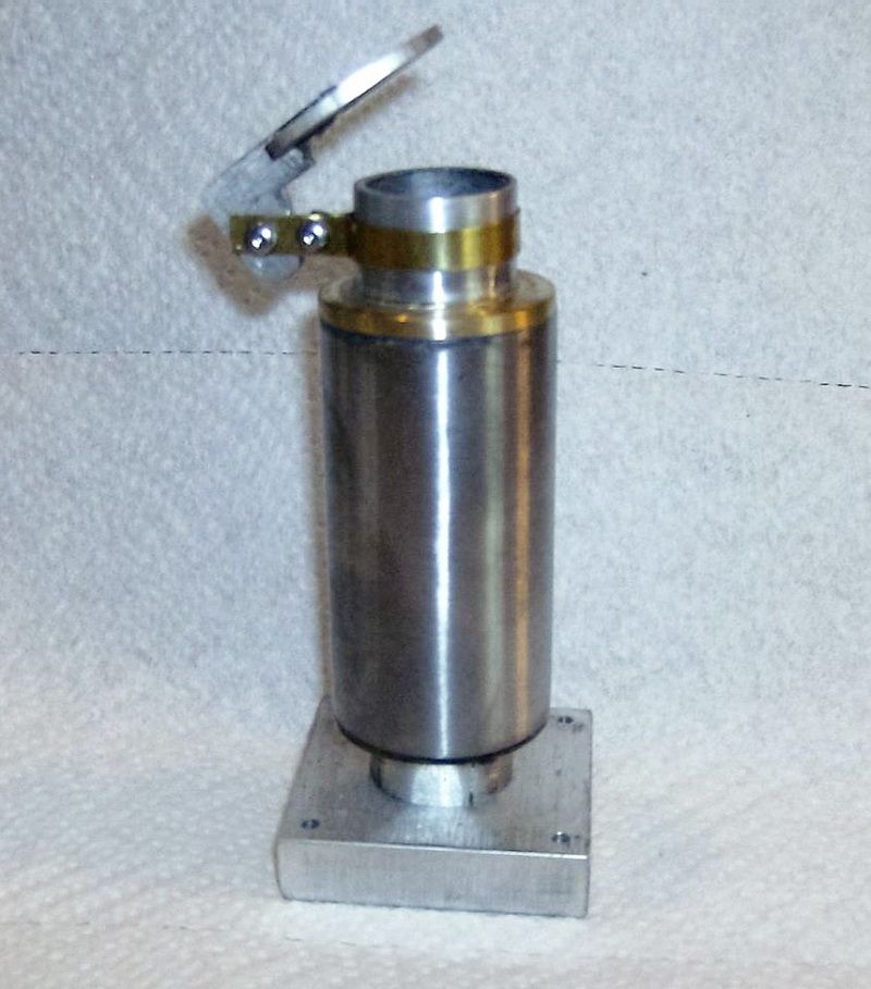
Made a couple of lathe acquisitions in the past year or so, including the Quick Change tool holder and the massive 6-inch 3-jaw lathe chuck. Jaws are removable and you can add custom aluminum jaws to these chucks to do custom turning like these wheels. I make my own aluminum jaws. You just need to know the keyway dimensions and bolt locations for the particular chuck you are using.

This photo was taken about 5 month ago when I had completed the wheels and axles. I redesigned the old journal boxes (shown earlier in this thread) and made it easier to do maintenance on the axle bearings. The new journals are shown in this photo and the bearings and axles are installed. Journals are all installed in the journal box pockets with the heavy duty suspension springs installed. The wheels have since been pressed onto the axles and the back to back and flange gauge is correct for 7-1/2 inch gauge track. You can also see one of the two motors setting between the loco wireframes. This is to make sure there is plenty of room to mount the motors and have clearance under the engine and rail. In this photo, the frame is upside down. I also needed to find out if I had the room for the 8-inch “woofer” speaker for the Phoenix Sound. Phoenix Sound in these ride-on locomotives will actually shake the ground adjacent to the engine (with amplifiers and woofer speakers-which this engine will have).

Close-up photo of the journal boxes, 3/4 inch diameter steel axle, springs between the journal box and the spring keepers. The ends of the axles are finished turned and ready to have the wheels pressed on. AND you can forget to install the two sprockets for the chain drive (#25 chain) BEFORE you press the wheels on! That is now completed :).

Close-up the journal box, journal box keepers and the bearing cap held by 4 hex head bolts. Cap is easily removed for access to the bearing and to help press the bearing out for replacement if needed.

Photo taken a couple of month ago. Actually sitting on it’s own four “feet” and on the lift rack for the first time. Engine rolls very easy. Had to c-clamp the wheels to prevent it rolling off the rack. Probably weighs about 90-95 pounds now.

Dry fitting the cab and hood. Stack with “rain flapper”. Jack Bodenman angle number board headlight. Made by the same Master Model Maker who made my Sunbeam Golden Glo headlights for my Baldwin electrics. Krypton gas light bulb, chromed sin casting copper reflector and curved headlight glass. Just like the prototype.

Fitting the sunshades and roof. There is a door and small step that is installed in the rear. Expecting new cast iron coupler pockets on Thursday and I can attach the Tom Bee cast steel automatic couplers.

Sitting next to it’s big sister’s, the two Baldwin electrics. Size comparison.

Still a good-sized locomotive next to the Baldwin electrics. I’m having a custom storage stand made for this engine in Markleeville, CA. But the Tamaeack Fire has delayed that welding project! :((